AD8150ASTZ Analog Devices Inc, AD8150ASTZ Datasheet - Page 24
AD8150ASTZ
Manufacturer Part Number
AD8150ASTZ
Description
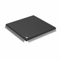
IC,Telecom Switching Circuit,QFP,184PIN,PLASTIC
Manufacturer
Analog Devices Inc
Datasheet
1.AD8150AST.pdf
(44 pages)
Specifications of AD8150ASTZ
Function
Crosspoint Switch
Circuit
1 x 33:17
Voltage Supply Source
Dual Supply
Voltage - Supply, Single/dual (±)
±3 V ~ 5.5 V
Operating Temperature
0°C ~ 85°C
Mounting Type
Surface Mount
Package / Case
184-LQFP
Lead Free Status / RoHS Status
Lead free / RoHS Compliant
Available stocks
Company
Part Number
Manufacturer
Quantity
Price
Company:

Part Number:
AD8150ASTZ
Manufacturer:
Analog Devices Inc
Quantity:
10 000


AD8150
To ensure proper operation, all outputs (including unused
output) must be pulled high, using external pull-up networks,
to a level within the output compliance range. If outputs from
multiple AD8150s are wired together, a single pull-up network
may be used for each output bus. The pull-up network should
be chosen to keep the output voltage levels within the output
compliance range at all times. Recommended pull-up networks
to produce PECL/ECL 100K- and 10K-compatible outputs are
shown in Figure 35. Alternatively, a separate supply can be used
to provide V
The output levels are simply:
The common-mode adjustment element (R
omitted if the input range of the receiver includes the positive
supply voltage. The bypass capacitors reduce common-mode
perturbations by providing an ac short from the common nodes
(V
When busing together the outputs of multiple AD8150s or
when running at high data rates, double termination of its
outputs is recommended to mitigate the impact of reflections
due to open transmission line stubs and the lumped capacitance
of the AD8150 output pins. A possible connection is shown in
Figure 36; the bypass capacitors provide an ac short from the
common nodes of the termination resistors to ground. To
COM
AD8150
OUTyyN
V
V
V
V
V
OUTyyP
) to ground.
OH
OL
COM
COM
SWING
Figure 35. Output Pull-Up Networks: a) ECL 100K, b) ECL 10K
=
=
=
=
V
V
COM
R
=
V
V
COM
COM
L
V
V
CC
CC
CC
, making R
V
OH
EE
V
Figure 34. Simplified Output Circuit
– 2V
−
−
−
CC
R
−
V
I
I
V
COM
OUT
OUT
COM
V
(
D
OL
R
R
COM
L
=
COM
COM
R
I
L
DISABLE
)
OUT
(
OUTyyP
and D
10
(
100
AD8150
R
K
OUTyyN
OUTyyP
L
K
Mode
V
COM
V
Mode
CC
EE
OUTyyN
I
unnecessary.
OUT
)
R
L
)
COM
V
or D
CC
D
V
COM
COM
COM
) may be
R
L
Rev. A | Page 24 of 44
maintain signal fidelity at high data rates, the stubs connecting
the output pins to the output transmission lines or load resistors
should be as short as possible.
In this case, the output levels are:
OUTPUT CURRENT SET PIN (REF)
A simplified schematic of the reference circuit is shown in
Figure 37. A single external resistor connected between the
REF pin and V
stages. This feature allows a choice of pull-up networks and
transmission line characteristic impedances while still achieving
a nominal output swing of 800 mV. At low data rates, substantial
power savings can be achieved by using lower output swings
and higher load resistances.
V
V
V
OH
OL
SWING
=
=
Figure 36. Double Termination of AD8150 Outputs
1.25V
V
V
AD8150
=
COM
COM
V
EE
OH
AD8150
Figure 37. Simplified Reference Circuit
AD8150
determines the output current for all output
−
−
OUTyyN
OUTyyP
OUTyyN
OUTyyP
( )
−
( )
3
1
V
4
4
OL
I
I
OUT
OUT
=
I
OUT
( )
1
R
R
R
/25
2
Z
Z
L
L
L
O
O
R
RECEIVER
I
L
OUT
V
CC
V
R
R
CC
V
COM
COM
R
L
L
R
R
SET
L
Z
Z
REF
V
O
O
EE
Related parts for AD8150ASTZ
Image
Part Number
Description
Manufacturer
Datasheet
Request
R

Part Number:
Description:
SENSOR GAS FOR CO/NO2 EXHAUST
Manufacturer:
GE Sensing
Datasheet:

Part Number:
Description:
±1.7g Dual-Axis IMEMS Accelerometer Evaluation Board
Manufacturer:
Analog Devices Inc
Datasheet:

Part Number:
Description:
Inertial Sensor Evaluation System
Manufacturer:
Analog Devices Inc
Datasheet:
Part Number:
Description:
Manufacturer:
Analog Devices Inc
Datasheet:
Part Number:
Description:
Manufacturer:
Analog Devices Inc
Datasheet:
Part Number:
Description:
Manufacturer:
Analog Devices Inc
Datasheet:
Part Number:
Description:
Manufacturer:
Analog Devices Inc
Datasheet:
Part Number:
Description:
Manufacturer:
Analog Devices Inc
Datasheet:
Part Number:
Description:
Manufacturer:
Analog Devices Inc
Datasheet:
Part Number:
Description:
Manufacturer:
Analog Devices Inc
Datasheet:
Part Number:
Description:
Manufacturer:
Analog Devices Inc
Datasheet:
Part Number:
Description:
Manufacturer:
Analog Devices Inc
Datasheet:
Part Number:
Description:
Manufacturer:
Analog Devices Inc
Datasheet: