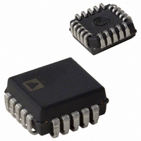
AD7821KPZ Analog Devices Inc, AD7821KPZ Datasheet - Page 9

AD7821KPZ
Manufacturer Part Number
AD7821KPZ
Description
8-BIT ATC CONVERTER IC
Manufacturer
Analog Devices Inc
Datasheet
1.AD7821KRZ-REEL.pdf
(16 pages)
Specifications of AD7821KPZ
Number Of Bits
8
Sampling Rate (per Second)
1M
Data Interface
Parallel
Number Of Converters
3
Power Dissipation (max)
50mW
Voltage Supply Source
Dual ±
Operating Temperature
-40°C ~ 85°C
Mounting Type
Surface Mount
Package / Case
20-LCC (J-Lead)
Lead Free Status / RoHS Status
Lead free / RoHS Compliant
Available stocks
Company
Part Number
Manufacturer
Quantity
Price
Company:
Part Number:
AD7821KPZ
Manufacturer:
Analog Devices Inc
Quantity:
10 000
Company:
Part Number:
AD7821KPZ-REEL
Manufacturer:
Analog Devices Inc
Quantity:
10 000
REV. B
SIGNAL-TO-NOISE RATIO AND DISTORTION
The dynamic performance of the AD7821 is evaluated by apply-
ing a very low distortion sine wave signal to the analog input
(V
Fourier Transform (FFT) plot is then generated from which
Signal-to-Noise Ratio (SNR) and harmonic distortion data are
obtained.
Figure 8 shows a 2048 point FFT plot of the AD7821 with an
input signal of 100.25 kHz. The SNR is 49.1 dB. It should be
noted that the harmonics are taken into account when calculat-
ing the SNR. The theoretical relationship between SNR and
resolution (N) is expressed by the following equation:
EFFECTIVE NUMBER OF BITS
By working backwards from Equation (1) it is possible to get a
measure of ADC performance expressed in effective number of
bits (N). A plot of the effective number of bits versus input
frequency is given in the Typical Performance Characteristics
section. The effective number of bits typically falls between 7.7
and 7.9, corresponding to SNR figures of 48.1 dB and 49.7 dB.
INTERMODULATION DISTORTION
For intermodulation distortion (IMD), an FFT plot consisting
of very low distortion sine waves at two frequencies is generated
by sampling an analog input applied to the ADC. Figure 9
shows a 2048 point plot for IMD.
HISTOGRAM PLOT
When a sine wave of specified frequency is applied to the V
of the AD7821 and several thousand samples are taken, it is
IN
SNR
) which is then sampled at a 512 kHz sampling rate. A Fast
=
(
6 02
.
N
Figure 9. FFT Plot for IMD
+
1 76
.
Figure 8. FFT Plot
)
dB
IN
input
(1)
–9–
possible to plot a histogram showing the frequency of occurrence
of each of the 256 ADC codes. A perfect ADC produces a
probability density function described by the equation:
where A is the peak amplitude of the sine wave and P(V) is the
probability of occurrence at a voltage V.
If a particular step is wider than the ideal 1 LSB width, then the
code associated with that step will accumulate more counts than
for the code for an ideal step. Likewise, a step narrower than the
ideal width will have fewer counts. Missing codes are easily seen
because a missing code means zero counts for a particular code.
The absence of large spikes in the plot indicates small differ-
ential nonlinearity.
Figure 10 shows a histogram plot for the AD7821, which corre-
sponds very well with the ideal shape. The plot indicates very
small differential nonlinearity and no missing codes for an input
frequency of 100.25 kHz.
In digital signal processing applications, where the AD7821 is
used to sample ac signals, it is essential that the signal sampling
occurs at exactly equal intervals. This minimizes errors due to
sampling uncertainty or jitter. A precise timer or clock source,
to start the ADC conversion process, is the best method of gen-
erating equidistant sampling intervals.
The two modes of operation given in the data sheet are suitable
for DSP applications because the sampling instant of the
AD7821 is well defined. V
WR or RD in the WR-RD or RD modes, respectively.
DIGITAL INTERFACE
The AD7821 has two basic interface modes which are determined
by the status of the MODE pin. When this pin is low, the
converter is in the RD mode, with this pin high, the AD7821 is
set up for the WR-RD mode.
The RD mode is designed for microprocessors that can be driven
into a WAIT state. A READ operation (i.e., CS and RD are taken
low) starts a conversion and data is read when the conversion is
complete. The WR-RD mode does not require microprocessor
WAIT states. A WRITE operation (i.e., CS and WR are taken
low) initiates a conversion, and a READ operation reads the
result when the conversion is complete.
Figure 10. Histogram Plot
P(V ) =
IN
is sampled on the falling edge of
π( A
2
− V
1
2
)
1/2
AD7821


