AD565ATD Analog Devices Inc, AD565ATD Datasheet - Page 6
AD565ATD
Manufacturer Part Number
AD565ATD
Description
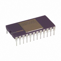
IC,D/A CONVERTER,SINGLE,12-BIT,BIPOLAR,DIP,24PIN
Manufacturer
Analog Devices Inc
Datasheet
1.AD565AJRZ-REEL.pdf
(12 pages)
Specifications of AD565ATD
Rohs Status
RoHS non-compliant
Settling Time
250ns
Number Of Bits
12
Data Interface
Parallel
Number Of Converters
1
Voltage Supply Source
Single Supply
Power Dissipation (max)
345mW
Operating Temperature
-55°C ~ 125°C
Mounting Type
Through Hole
Package / Case
24-CDIP (0.600", 15.24mm)
Lead Free Status / RoHS Status
Available stocks
Company
Part Number
Manufacturer
Quantity
Price

Part Number:
AD565ATD
Manufacturer:
ADI/亚德诺
Quantity:
20 000
Part Number:
AD565ATD/883
Manufacturer:
ADI/亚德诺
Quantity:
20 000


AD565A/AD566A
ABSOLUTE MAXIMUM RATINGS
V
V
Voltage on DAC Output (Pin 9) . . . . . . . . . . . . –3 V to +12 V
Digital Inputs (Pins 13 to 24) to
REF IN to Reference Ground . . . . . . . . . . . . . . . . . . . . ± 12 V
Bipolar Offset to Reference Ground . . . . . . . . . . . . . . . ± 12 V
10 V Span R to Reference Ground . . . . . . . . . . . . . . . . ± 12 V
20 V Span R to Reference Ground . . . . . . . . . . . . . . . . ± 24 V
REF OUT (AD565A) . . . . . Indefinite Short to Power Ground
Power Dissipation . . . . . . . . . . . . . . . . . . . . . . . . . . 1000 mW
Model
AD565AJD
AD565AJR
AD565AKD
AD565ASD
AD565ATD
NOTES
1
2
Model
AD566AJD
AD566AKD
AD566ASD
AD566ATD
NOTES
1
2
CAUTION
ESD (electrostatic discharge) sensitive device. Electrostatic charges as high as 4000 V readily
accumulate on the human body and test equipment and can discharge without detection. Although the
AD565A/AD566A features proprietary ESD protection circuitry, permanent damage may occur on
devices subjected to high energy electrostatic discharges. Therefore, proper ESD precautions are
recommended to avoid performance degradation or loss of functionality.
For details on grade and package offerings screened in accordance with MIL-STD-883, refer to the Analog Devices Military Products Databook or current/883B data sheet.
D = Ceramic DIP, R = SOIC.
For details on grade and package offerings screened in accordance with MIL-STD-883, refer to the Analog Devices Military Products Databook or current/883B data sheet.
D = Ceramic DIP.
CC
EE
Power Ground . . . . . . . . . . . . . . . . . . . . . . –1.0 V to +7.0 V
to Power Ground (AD565A) . . . . . . . . . . . . 0 V to –18 V
to Power Ground . . . . . . . . . . . . . . . . . . . . . 0 V to +18 V
1
1
Max Gain
T.C. (ppm
of F.S./
50
50
20
30
15
Max Gain
T.C. (ppm
of F.S./
10
3
10
3
°
°
C)
C)
Momentary Short to V
Temperature
Range
0°C to +70°C
0°C to +70°C
0°C to +70°C
–55°C to +125°C
–55°C to +125°C
Linearity
Temperature
Range
0°C to +70°C
0°C to +70°C
–55°C to +125°C
–55°C to +125°C
AD565A ORDERING GUIDE
AD566A ORDERING GUIDE
CC
–6–
GROUNDING RULES
The AD565A and AD566A use separate reference and power
grounds to allow optimum connections for low noise and high
speed performance. These grounds should be tied together at one
point, usually the device power ground. The separate ground
returns minimize current flow in low level signal paths. In this
way, logic return currents are not summed into the same return
path with analog signals.
Linearity
Error Max
@ +25
± 1/2 LSB
± 1/2 LSB
± 1/4 LSB
± 1/2 LSB
± 1/4 LSB
Error Max
@ +25
± 1/2 LSB
± 1/4 LSB
± 1/2 LSB
± 1/4 LSB
°
°
C
C
Package
Options
Ceramic (D-24)
SOIC (RW-28)
Ceramic (D-24)
Ceramic (D-24)
Ceramic (D-24)
Package
Option
Ceramic (D-24
Ceramic (D-24)
Ceramic (D-24)
Ceramic (D-24)
WARNING!
2
2
ESD SENSITIVE DEVICE
REV.E
Related parts for AD565ATD
Image
Part Number
Description
Manufacturer
Datasheet
Request
R

Part Number:
Description:
±1.7g Dual-Axis IMEMS Accelerometer Evaluation Board
Manufacturer:
Analog Devices Inc
Datasheet:

Part Number:
Description:
Inertial Sensor Evaluation System
Manufacturer:
Analog Devices Inc
Datasheet:
Part Number:
Description:
Manufacturer:
Analog Devices Inc
Datasheet:
Part Number:
Description:
Manufacturer:
Analog Devices Inc
Datasheet:
Part Number:
Description:
Manufacturer:
Analog Devices Inc
Datasheet:
Part Number:
Description:
Manufacturer:
Analog Devices Inc
Datasheet:
Part Number:
Description:
Manufacturer:
Analog Devices Inc
Datasheet:
Part Number:
Description:
Manufacturer:
Analog Devices Inc
Datasheet:
Part Number:
Description:
Manufacturer:
Analog Devices Inc
Datasheet:
Part Number:
Description:
Manufacturer:
Analog Devices Inc
Datasheet:
Part Number:
Description:
Manufacturer:
Analog Devices Inc
Datasheet:
Part Number:
Description:
Manufacturer:
Analog Devices Inc
Datasheet:
Part Number:
Description:
Manufacturer:
Analog Devices Inc
Datasheet: