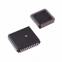
AD53508JP Analog Devices Inc, AD53508JP Datasheet - Page 7

AD53508JP
Manufacturer Part Number
AD53508JP
Description
IC,ATE Circuit,LDCC,44PIN,PLASTIC
Manufacturer
Analog Devices Inc
Datasheet
1.AD53508JP.pdf
(8 pages)
Specifications of AD53508JP
Rohs Status
RoHS non-compliant
Applications
Testing Equipment
Interface
Analog
Voltage - Supply
14 V ~ 15.75 V
Package / Case
44-PLCC
Mounting Type
Surface Mount
Lead Free Status / RoHS Status
Available stocks
Company
Part Number
Manufacturer
Quantity
Price
Company:
Part Number:
AD53508JP
Manufacturer:
Analog Devices Inc
Quantity:
10 000
IN CURRENT FORCE WITH VOLTAGE MEASURE OR
VERIFY CURRENT FORCE
The linearity tests for forcing current at the FORCE pin:
1. The FORCE pin is loaded with a voltage source.
2. The two ranges of CURRENT FORCE ranges (2 mA and
3. Using these endpoints, gain nonlinearity is computed and
4. Computations for F1 are:
The linearity test for measuring voltage is as follows (at the
MEAS_OUT pin):
1. The endpoints of the linearity curve are determined by the
2. Using these endpoints, gain nonlinearity is computed and
3. Computations for M1 are:
CURRENT FORCE WITH VOLTAGE MEASURE
(2 mA RANGE)
1. DAC1 = 5 V.
2. FORCE pin loaded with 9 V source.
3. Measure current at FORCE.
4. Measure voltage at MEAS_OUT.
5. V
6. Measure current at FORCE and compare to 3.
200 µA) correspond to F1 and F2. The endpoints of the
linearity curve are determined by full scale (or LOW), and
the full scale (or HIGH) readings at the same FORCE pin
voltage.
tested at the 1/4 scale, 1/2 scale, and 3/4 scale points.
F1 × 0.25 = LOW + 1 × (HIGH – LOW)/4
F1 × 0.50 = LOW + 2 × (HIGH – LOW)/4
F1 × 0.75 = LOW + 3 × (HIGH – LOW)/4
Where LOW = –Full Scale and HIGH = +Full Scale.
–full scale (or LOW), and the +full scale (or HIGH) readings.
tested at the 1/4 scale, 1/2 scale, and 3/4 scale points.
M1 × 0.25 = LOW + 1 × (HIGH – LOW)/4
M1 × 0.50 = LOW + 2 × (HIGH – LOW)/4
M1 × 0.75 = LOW + 3 × (HIGH – LOW)/4
Where LOW = –Full Scale, and HIGH = +Full Scale.
CC
= 15 V.
MEAS OUT
VOLTAGE
FORCING
DAC1
DAC2
DSR
CON
2.5V
S1
S6
S7
ENABLE
OUTPUT
AD53508
S2
S3
VM
IM
SENSE
IF
VF
S4
S5
DIFF
1.25R
1.25R
MAIN
EXT RC
7. Measure voltage at MEAS_OUT and compare to 4.
8. V
9. DAC1 = 0 V.
10. FORCE pin loaded with –4 V source.
11. Measure current at FORCE.
12. Measure voltage at MEAS_OUT.
13. V
14. Measure current at FORCE and compare to 11.
15. Measure voltage at MEAS_OUT and compare to 12.
16. V
VOLTAGE FORCE WITH CURRENT MEASURE
(2 mA RANGE)
1. DAC1 = 9 V.
2. FORCE pin loaded with 2 mA current source.
3. Measure voltage at FORCE.
4. Measure current at MEAS_OUT.
5. V
6. Measure voltage at FORCE and compare to 3:
7. Measure current at MEAS_OUT and compare to 4:
8. V
9. DAC1 = –4 V.
10. FORCE pin loaded with 2 mA current sink.
11. Measure voltage at FORCE.
12. Measure current at MEAS_OUT.
13. V
14. Measure voltage at FORCE and compare to 11:
15. Measure current at MEAS_OUT and compare to 12.
16. V
R
R
Limit = ± 237 µV.
Limit = ± 237 µV.
Limit = ± 474 µV.
CC
EE
EE
CC
CC
EE
EE
INTEGRATE
200 A
10k
= –9.5 V.
= –10 V.
= –9.5 V.
= –10 V.
= 15 V.
= 14.25 V.
= 15 V.
40pF
S10
2mA
1k
UNITY
C1
R1
R2
S8
S9
INT/IM
GUARD
≤
S11
S12
S13
S14
S15
S16
S18
S17
FORCE
GUARD
SENSE
AD53508


