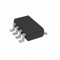
AD5227BUJZ100-R2 Analog Devices Inc, AD5227BUJZ100-R2 Datasheet - Page 12

AD5227BUJZ100-R2
Manufacturer Part Number
AD5227BUJZ100-R2
Description
IC,Digital Potentiometer,TSSOP,8PIN,PLASTIC
Manufacturer
Analog Devices Inc
Datasheet
1.AD5227BUJZ10-RL7.pdf
(16 pages)
Specifications of AD5227BUJZ100-R2
Taps
64
Resistance (ohms)
100K
Number Of Circuits
1
Temperature Coefficient
35 ppm/°C Typical
Memory Type
Volatile
Interface
Up/Down Counter
Voltage - Supply
2.7 V ~ 5.5 V
Operating Temperature
-40°C ~ 105°C
Mounting Type
Surface Mount
Package / Case
TSOT-23-8, TSOT-8
Resistance In Ohms
100K
Lead Free Status / RoHS Status
Lead free / RoHS Compliant
Available stocks
Company
Part Number
Manufacturer
Quantity
Price
Company:
Part Number:
AD5227BUJZ100-R2
Manufacturer:
AD
Quantity:
11 500
AD5227
APPLICATIONS
MANUAL CONTROL WITH TOGGLE AND
PUSHBUTTON SWITCHES
The AD5227’s simple interface allows it to be used with
mechanical switches for simple manual operation. The states of
the CS and U/ D can be selected by toggle switches and the CLK
input can be controlled by a pushbutton switch. Because of the
numerous bounces due to contact closure, the pushbutton
switch should be debounced by flip-flops or by the ADM812 as
shown in
MANUAL CONTROL WITH ROTARY ENCODER
Figure 32 shows another way of using AD5227 to emulate
mechanical potentiometer in a rotary knob operation. The
rotary encoder U1 has a C ground terminal and two out-of-
phase signals, A and B. When U1 is turned clockwise, a pulse
generated from the B terminal leads a pulse generated from the
A terminal and vice versa. Signals A and B of U1 pass through a
quadrature decoder U2 that translates the phase difference
between A and B of U1 into compatible inputs for U3 AD5227.
Therefore, when B leads A (clockwise), U2 provides the AD5227
with a logic high U/ D signal, and vice versa. U2 also filters
noise, jitter, and other transients as well as debouncing the
contact bounces generated by U1.
RE11CT-V1Y12-EF2CS
ENCODER
ROTARY
U1
B
C
A
10kΩ
Figure 31
R1
Figure 31. Manual Push Button Up/Down Control
UP/DOWN
5V
INCREMENT
10kΩ
R2
Figure 32. Manual Rotary Control
.
10kΩ
R3
MR
5V
ADM812
1
2
3
4
GND
V
RBIAS
V
VSS
A
QUADRATURE
RESET
CC
DD
DECODER
LS7084
U2
X4/X1
CLK
U/D
B
8
7
6
5
CS
U/D
CLK
AD5227
A1
1
2
3
4
POTENTIOMETER
CLK
U/D
A1
GND
AD5227
DIGITAL
U3
V
W1 5
CS
B1 6
DD
8
7
B1
W1
Rev. B | Page 12 of 16
ADJUSTABLE LED DRIVER
The AD5227 can be used in many electronics-level adjustments
such as LED drivers for LCD panel backlight control. Figure 33
shows an adjustable LED driver. The AD5227 sets the voltage
across the white LED D1 for the brightness control. Since U2
handles up to 250 mA, a typical white LED with V
requires a resistor, R1, to limit the U2 current. This circuit is
simple but not power-efficient, therefore the U2 shutdown pin
can be toggled with a PWM signal to conserve power.
ADJUSTABLE CURRENT SOURCE FOR LED DRIVER
Since LED brightness is a function of current rather than
forward voltage, an adjustable current source is preferred over a
voltage source as shown in Figure 34.
The load current can be found as the V
divided by R
5V
PWM
I =
D
C1
1μF
V
SD
ADP3333
IN
ARM-1.5
Figure 34. Adjustable Current Source for LED Driver
R
V
SET
C2
0.1μF
U1
GND
WB
SET
Figure 33. Low Cost Adjustable LED Driver
V
.
CS
CLK
U/D
OUT
V
DD
5V
5V
AD5227
A
10kΩ
B
GND
U1
W
V
CS
CLK
U/D
DD
GND
+
AD5227
B
10kΩ
A
R1
418kΩ
–
V+
AD8591
V–
AD8591
5V
5V
U3
U2
W
U2
WB
V+
V–
0.1μF
PWM
of the AD5227
–
+
C3
SD
6Ω
R1
F
R
0.1Ω
D1
SET
of 3.5 V
VL
WHITE
LED
D1
ID
(5)


