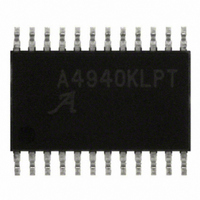
A4940KLPTR-T Allegro Microsystems Inc, A4940KLPTR-T Datasheet - Page 7

A4940KLPTR-T
Manufacturer Part Number
A4940KLPTR-T
Description
FULL BRIDGE MOSFET PRE-DRIVER
Manufacturer
Allegro Microsystems Inc
Datasheet
1.A4940KLPTR-T.pdf
(14 pages)
Specifications of A4940KLPTR-T
Configuration
H Bridge
Input Type
Non-Inverting
Delay Time
35ns
Number Of Configurations
1
Number Of Outputs
4
Voltage - Supply
5.5 V ~ 50 V
Operating Temperature
-40°C ~ 150°C
Mounting Type
Surface Mount
Package / Case
24-TSSOP Exposed Pad, 24-eTSSOP, 24-HTSSOP
Lead Free Status / RoHS Status
Lead free / RoHS Compliant
Current - Peak
-
High Side Voltage - Max (bootstrap)
-
Lead Free Status / RoHS Status
Lead free / RoHS Compliant
Other names
620-1319-2
Available stocks
Company
Part Number
Manufacturer
Quantity
Price
Company:
Part Number:
A4940KLPTR-T
Manufacturer:
ALLEGRO
Quantity:
356
Part Number:
A4940KLPTR-T
Manufacturer:
ALLEGRO/雅丽高
Quantity:
20 000
A4940
on the upper half of the drive, sourcing current to the gate of the
high-side MOSFET in the external motor-driving bridge, turning
it on. GHx going low turns on the lower half of the drive, sinking
current from the external MOSFET gate circuit to the correspond-
ing Sx pin, turning off the MOSFET.
CA and CB Pins These are the high-side connections for the
bootstrap capacitors and are the positive supply for the high-side
gate drives. The bootstrap capacitors are charged to approxi-
mately V
When the Sx output swings high, the charge on the bootstrap
capacitor causes the voltage at the corresponding Cx terminal to
rise with the output to provide the boosted gate voltage needed
for the high-side MOSFETs.
RDEAD Pin This pin controls internal generation of dead time
during MOSFET switching. Cross-conduction is prevented
by the gate drive circuits, which introduce a dead time, t
between switching one MOSFET off and the complementary
MOSFET on.
• When an external resistor greater than 3 kΩ is connected be-
• When RDEAD is connected directly to VDD, t
Logic Control Inputs
Four low voltage-level digital inputs provide control for the gate
drives. These logic inputs all have a typical hysteresis of 500 mV
to improve noise performance. They provide individual direct
control over each power MOSFET, subject to cross-conduction
prevention, and can be used together to provide fast decay or
slow decay with high-side or low-side recirculation.
AHI, ALO, BHI and BLO Pins These directly control the gate
drives. The xHI inputs control the high-side drives and the xLO
tween RDEAD and AGND, the dead time is derived from the
resistor value.
a value of 6 μs typical.
REG
Table 1. Input Logic
RESET
when the associated output Sx terminal is low.
H
H
H
H
L
xHI
H
H
L
L
x
xLO
H
H
L
L
x
Pin Setting
GHx
H
Z
L
L
L
DEAD
GLx
Automotive Full Bridge MOSFET Driver
H
H
L
L
Z
defaults to
DEAD
Sx
,
H
Z
Z
L
L
High side MOSFET conducting
Low Side MOSFET conducting
Low Side MOSFET conducting – cross-conduction prevention
High side and low side off
All gate drives inactive, all MOSFETs off
inputs control the low-side drives. Internal lockout logic ensures
that the high-side output drive and low-side output drive cannot
be active simultaneously. Table 1 shows the logic truth table.
RESET Pin This is an active-low input, and when active it
allows the A4940 to enter sleep mode. When RESET is held low,
the regulator and all internal circuitry are disabled and the A4940
enters sleep mode. Before fully entering sleep mode, there is a
short delay while the regulator decoupling and storage capacitors
discharge. This typically takes a few milliseconds, depending on
the application conditions and component values.
During sleep mode, current consumption from the VBB supply
is reduced to a minimal level. In addition, latched faults and the
corresponding fault flags are cleared. When the A4940 is coming
out of sleep mode, the protection logic ensures that the gate drive
outputs are off until the charge pump reaches its correct operat-
ing condition. The charge pump stabilizes in approximately 3 ms
under nominal conditions.
RESET can be used also to clear latched fault flags without enter-
ing sleep mode. To do so, hold RESET low for the reset pulse
time, t
age fault that disables the outputs.
Note that the A4940 can be configured to start without any exter-
nal logic input. To do so, pull up the RESET pin to V
of an external resistor. The resistor value should be between
20 and 33 kΩ.
Diagnostics
Several diagnostic features are integrated into the A4940 to
provide indication of fault conditions. In addition to system wide
faults such as undervoltage and overtemperature, the A4940 inte-
grates individual bootstrap voltage monitors for each bootstrap
capacitor.
RES
. This clears the latched bootstrap capacitor undervolt-
Mode of Operation
115 Northeast Cutoff
1.508.853.5000; www.allegromicro.com
Allegro MicroSystems, Inc.
Worcester, Massachusetts 01615-0036 U.S.A.
BB
by means
7


