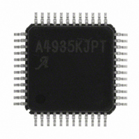
A4935KJPTR-T Allegro Microsystems Inc, A4935KJPTR-T Datasheet - Page 10

A4935KJPTR-T
Manufacturer Part Number
A4935KJPTR-T
Description
AUTO THREE-PHASE MOSFET PREDRIVER
Manufacturer
Allegro Microsystems Inc
Datasheet
1.A4935KJPTR-T.pdf
(24 pages)
Specifications of A4935KJPTR-T
Configuration
3 Phase Bridge
Input Type
PWM
Delay Time
90ns
Number Of Configurations
1
Number Of Outputs
3
Voltage - Supply
5.5 V ~ 50 V
Operating Temperature
-40°C ~ 150°C
Mounting Type
Surface Mount
Package / Case
48-LFQFP Exposed Pad
Operating Temperature Classification
Automotive
Operating Supply Voltage (min)
3V
Operating Supply Voltage (max)
5.5V
Lead Free Status / RoHS Status
Lead free / RoHS Compliant
Current - Peak
-
High Side Voltage - Max (bootstrap)
-
Lead Free Status / Rohs Status
Compliant
Other names
620-1300-2
A4935KJPTR-T
A4935KJPTR-T
Available stocks
Company
Part Number
Manufacturer
Quantity
Price
Company:
Part Number:
A4935KJPTR-T
Manufacturer:
Allegro Microsystems Inc
Quantity:
135
Company:
Part Number:
A4935KJPTR-T
Manufacturer:
Allegro MicroSystems, LLC
Quantity:
10 000
Part Number:
A4935KJPTR-T
Manufacturer:
ALLEGRO/雅丽高
Quantity:
20 000
A4935
• Setting PWML low turns off active low-side drives and turns on
• PWMH and PWML may also be connected together and driven
COAST Pin
outputs, GHx and GLx, and turns off all external FETs. This can
be used to protect the FETs and the motor in the case of a short
circuit. Using COAST does not clear any faults, so the fault flags
can still be decoded and the fault register data word can be read.
Because COAST turns off all the external FETs, it can also be used
to provide fast-decay PWM without synchronous rectification.
RESET Pin
allows the A4935 to enter sleep mode. When RESET is held low
for longer than the reset pulse time, t
internal circuitry are disabled and the A4935 enters sleep mode.
During sleep mode, current consumption from the VBB and VDD
supplies is reduced to a minimal level. In addition, latched faults
and the corresponding fault flags are cleared. When the A4935 is
coming out of sleep mode, the protection logic ensures that the
gate drive outputs are off until the charge pump reaches its
Table 1. Phase Control Truth Table
RDEAD
x = don’t care, HS = high-side FET active, LS = low-side FET active, Z = high impedance, both FETs off, U = undefined, SR = synchronous rectification
the complementary high-side drives. This provides low-side–
chopped slow-decay PWM with synchronous rectification.
with a single PWM signal. This provides fast-decay PWM with
synchronous rectification.
>0.2 V
AGND
AGND
AGND
AGND
x
x
x
x
x
x
x
x
x
x
x
RESET
An active-low input, which forces low all gate drive
This is an active-low input, and when active it
1
1
1
1
1
1
1
1
1
1
1
1
0
1
1
1
CCEN
0
1
x
x
x
x
x
x
x
x
x
x
x
x
x
x
COAST
x
1
1
x
1
1
1
1
1
1
1
1
x
0
1
1
Inputs
RES
PWMH
, the regulator and all
x
1
1
x
0
0
1
1
0
0
1
0
x
x
1
1
PWML
1
1
1
1
0
0
0
0
0
1
1
1
x
x
x
x
xHI
Automotive 3-Phase MOSFET Driver
0
0
1
1
0
1
0
1
0
1
1
1
x
x
1
1
xLO
0
1
0
1
1
0
1
0
1
0
1
1
1
1
x
x
correct operating condition. The charge pump stabilizes in
approximately 3 ms under nominal conditions.
RESET can be used also to clear latched fault flags without
entering sleep mode. To do so, hold RESET low for less then the
reset pulse time, t
the outputs, such as short circuit detection or bootstrap capacitor
undervoltage, and also clears the fault register.
Note that the A4935 can be configured to start without any exter-
nal logic input. To do so, pull up the RESET pin to V
of an external resistor. The resistor value should be between
20 and 33 kΩ.
CCEN Pin
side and the low-side external FETs of any phase to be active at
the same time, enabling cross-conduction. As an extra level of
safety, cross-conduction can only occur when RDEAD is tied to
AGND and CCEN is set high. If the CCEN input is inadvertently
disconnected from the controller, an internal pull-down resistor
ensures that the outputs revert to a safe condition.
ESF Pin
action that is taken when certain faults are detected. See the Fault
Protection and Diagnostics section for details.
GHx
H
H
H
H
H
H
L
L
L
L
L
L
L
Z
L
L
This is the Enable Stop on Fault input. It determines the
This input provides an override to allow both the high-
Outputs
GLx
H
H
H
H
H
H
L
L
L
L
L
L
L
Z
L
L
RES
. This clears any latched fault that disables
HS
HS
HS
HS
HS
Sx
LS
LS
LS
LS
LS
U
Z
Z
Z
Z
Z
115 Northeast Cutoff
1.508.853.5000; www.allegromicro.com
Phase disabled
Phase sinking
Phase sourcing
Phase disabled
Sink; high-side PWM on other phases
Slow decay, SR; low-side recirculation
Slow decay, SR; high-side recirculation
Source; low-side PWM on other phases
Fast decay, SR
Fast decay, SR
Slow decay, SR; high-side recirculation
Slow decay, SR; low-side recirculation
Low power shutdown
Coast
Phase disabled
Cross-conduction
Allegro MicroSystems, Inc.
Worcester, Massachusetts 01615-0036 U.S.A.
Comment
BB
by means
10


