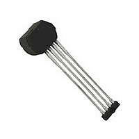
A1421LK-T Allegro Microsystems Inc, A1421LK-T Datasheet - Page 13

A1421LK-T
Manufacturer Part Number
A1421LK-T
Description
IC,HALL-EFFECT SENSOR,SINGLE-ENDED,SIP,4PIN,PLASTIC
Manufacturer
Allegro Microsystems Inc
Type
Special Purposer
Datasheet
1.A1421LK-T.pdf
(15 pages)
Specifications of A1421LK-T
Rohs Compliant
YES
Sensing Range
27.5G Trip, -12.5G Release
Voltage - Supply
4 V ~ 26.5 V
Current - Supply
7mA
Current - Output (max)
25mA
Output Type
Digital, Open Collector
Features
High Precision
Operating Temperature
-40°C ~ 150°C
Package / Case
4-SIP
Magnetic Type
Monolithic
Operating Supply Voltage (min)
4V
Operating Supply Voltage (typ)
12V
Operating Supply Voltage (max)
26.5V
Output Current
25mA
Mag Sensor Operate Point (g)
27.5Gs
Mag Sensor Release Point (g)
-12.5Gs
Mag Sensor Hysteresis(g)
15Gs
Package Type
SIP
Pin Count
4
Mounting
Through Hole
Operating Temp Range
-40C to 150C
Operating Temperature Classification
Automotive
Lead Free Status / RoHS Status
Lead free / RoHS Compliant
Lead Free Status / RoHS Status
Lead free / RoHS Compliant
A1421, A1422,
and
in the Characteristic Data section quantify the effect of the input
signal amplitude on the phase shift of the output. Positive values
of delay indicate a lagging output, while negative values indicate
a leading output.
AC-Coupled Operation
Steady-state magnet and system offsets are eliminated using an
on-chip differential bandpass filter. The upper and lower cut-off
frequencies of this patented filter are set using an internal inte-
grated capacitor. The differential structure of this filter improves
the ability of the IC to reject single-ended noise on the GND
or VCC lines and, as a result, makes the device more resistant
to EMI (electromagnetic interference) typically seen in hostile
remote-sensing environments.
Power Supply Protection
The device contains an on-chip voltage regulator and can operate
over a wide supply voltage range. In applications that operate the
device from an unregulated power supply, transient protection
must be added externally. For applications using a regulated line,
EMI/RFI protection may still be required. The circuit shown
in figure 3 is the most basic configuration required for proper
device operation.
A1423
Figure 2. Comparative typical output characteristics. This chart illustrates the switchpoints and the output polarities of the A1421,
A1422, and the A 1423. Characteristics shown without delay, see characteristic data charts for delay and phase shift contributions.
and Output Signal, V
and Output Signal, V
and Output Signal, V
1421 Switching State
1422 Switching State
1423 Switching State
Applied Magnetic
Field, B
diff
OUT
OUT
OUT
–15.0
–65.0
65.0
15.0
0.0
High Precision Hall Effect AC-Coupled Differential
Off
B
B
B
RP(typ)1422
RP(typ)1423
RP(typ)1421
On
On
Sensor IC with Integrated Filter Capacitor
Typical Circuit
A pull-up resistor, R
put terminals, as shown in figure 3. Also, the auxilliary terminal,
TEST, must be connected externally to the GND terminal.
Figure 3. Basic application circuit
with the output driver.
B
OP(typ)1421, 1422
On
Off
Off
0.1 uF
B
OP(typ)1423
4
GND
A1421, A1422
PU
or A1423
VCC
TEST
, is required between the supply and out-
3
1
VOUT
115 Northeast Cutoff
1.508.853.5000; www.allegromicro.com
Allegro MicroSystems, Inc.
Worcester, Massachusetts 01615-0036 U.S.A.
. A pull-up resistor, R
2
Off
On
On
t+
R
PU
PU
V
, is required
V
S
OUT
13


