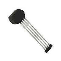
A1421LK-T Allegro Microsystems Inc, A1421LK-T Datasheet - Page 12

A1421LK-T
Manufacturer Part Number
A1421LK-T
Description
IC,HALL-EFFECT SENSOR,SINGLE-ENDED,SIP,4PIN,PLASTIC
Manufacturer
Allegro Microsystems Inc
Type
Special Purposer
Datasheet
1.A1421LK-T.pdf
(15 pages)
Specifications of A1421LK-T
Rohs Compliant
YES
Sensing Range
27.5G Trip, -12.5G Release
Voltage - Supply
4 V ~ 26.5 V
Current - Supply
7mA
Current - Output (max)
25mA
Output Type
Digital, Open Collector
Features
High Precision
Operating Temperature
-40°C ~ 150°C
Package / Case
4-SIP
Magnetic Type
Monolithic
Operating Supply Voltage (min)
4V
Operating Supply Voltage (typ)
12V
Operating Supply Voltage (max)
26.5V
Output Current
25mA
Mag Sensor Operate Point (g)
27.5Gs
Mag Sensor Release Point (g)
-12.5Gs
Mag Sensor Hysteresis(g)
15Gs
Package Type
SIP
Pin Count
4
Mounting
Through Hole
Operating Temp Range
-40C to 150C
Operating Temperature Classification
Automotive
Lead Free Status / RoHS Status
Lead free / RoHS Compliant
Lead Free Status / RoHS Status
Lead free / RoHS Compliant
A1421, A1422,
and
The A1421, A1422, and A1423 are versatile high-precision dif-
ferential sensor ICs that can be used in a wide range of applica-
tions. Proper choice of the target material and shape, magnet
material and shape, and assembly techniques enables large
working air gaps and high switchpoint accuracy over the device
operating temperature range.
Device Operation
The device IC contains two integrated Hall transducers that are
used to differentially respond to a magnetic field across the sur-
face of the IC. Referring to figure 1, which shows curves for the
A1421 as an example, the trigger switches the output when the
differential magnetic field crosses the B
in strength (referred to as the positive direction). In the example,
the A1421 output voltage switches high (off), and switches the
output low (on) when the differential magnetic field crosses B
while decreasing (the negative direction).
The operation is achieved through the use of two separate com-
parators. One comparator has a positive hysteresis, B
A1423
1421 Output Signal, V
Comparator 1, A1421
Comparator 2, A1421
1421 Switching State
Applied Magnetic
Figure 1. Typical output characteristics with dual comparator operation. The example shown is for the A1421. Characteristics
shown without delay, see characteristic data charts for delay and phase shift contributions.
Field, B
diff
OUT
15.0
0.0
OP
High Precision Hall Effect AC-Coupled Differential
Off
level while increasing
Applications Information
HYS1
, and
Sensor IC with Integrated Filter Capacitor
RP
B
RP(typ)1421
the other a negative hysteresis, B
switches at the B
and the other switches at the B
ential signal. The hysteresis on each comparator precludes false
switching on noise or target jitter.
The behavior is similar for the A1422 and the A1423. The
switchpoints are as shown in the magnetic charactersitics table,
and the output polarity is inverted. This is illustrated in figure 2,
on the next page.
Start-up
During power-on time, t
Beyond this time, if the applied magnetic field, B
than B
minate. V
settling time, t
Delay
The bandpass filter induces delay in the output signal, V
ative to the applied magnetic field, B
B
HYS2
On
B
HYS
OP(typ)1421
OUT
, the switching state and V
will be valid for B
Settling
B
OP
HYS1
crossing on an increasing differential signal
, has also elapsed.
PO
115 Northeast Cutoff
1.508.853.5000; www.allegromicro.com
, the output signal, V
Allegro MicroSystems, Inc.
Worcester, Massachusetts 01615-0036 U.S.A.
RP
HYS2
diff
crossing on a decreasing differ-
Off
> B
OUT
diff
. Therefore, one comparator
HYS
. Simulation data shown
polarity are indeter-
, after the additional
OUT
diff
, is high.
, is smaller
OUT
, rel-
12


