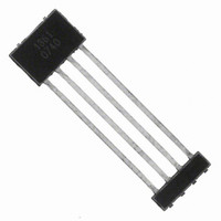
A1361LKTTN-T Allegro Microsystems Inc, A1361LKTTN-T Datasheet - Page 24

A1361LKTTN-T
Manufacturer Part Number
A1361LKTTN-T
Description
IC,HALL-EFFECT SENSOR,SINGLE-ENDED,BICMOS,SIP,4PIN,PLASTIC
Manufacturer
Allegro Microsystems Inc
Type
Linear - Unipolar, Bipolarr
Datasheet
1.A1360LKTTN-T.pdf
(25 pages)
Specifications of A1361LKTTN-T
Sensing Range
1.4mV/G ~ 4.5mV/G
Voltage - Supply
4.5 V ~ 5.5 V
Current - Supply
12mA
Current - Output (max)
10mA
Output Type
Analog, Ratiometric
Features
Programmable
Operating Temperature
-40°C ~ 150°C
Package / Case
4-SIP
Lead Free Status / RoHS Status
Lead free / RoHS Compliant
Other names
620-1234-2
A1360, A1361,
and A1362
In low-frequency sensing applications, it is often advantageous
to add a simple RC filter to the output of the sensor IC. Such a
low-pass filter improves the signal-to-noise ratio, and therefore
the resolution, of the device output signal. However, the addition
of an RC filter to the output of a sensor IC can result in undesir-
able device output attenuation — even for DC signals.
Signal attenuation, ∆V
effect between the resistance of the external filter, R
ure 10), and the input impedance and resistance of the customer
interface circuit, R
divider is given by:
Even if R
ual resistance values will most likely drift by different amounts
Figure 10. When a low pass filter is constructed externally
to a standard Hall effect device, a resistive divider may
exist between the filter resistor, R
load resistance, R
area) will cause excessive attenuation, as given by the
transfer function shown in equation 16.
Figure 11. The FILTER pin provided
on the A136x device allows separate
control of SNR, avoiding the attenua-
tion effects from the standard resistor
divider solution, shown in figure 10.
EXT
∆V
ATT
and R
INTFC
=
INTFC
V
INTFC
OUT
. This resistive divider (shaded
Improving Sensing System Accuracy Using the FILTER Pin
ATT
. The transfer function of this resistive
⎛
⎜ ⎜
⎝
are designed to match, the two individ-
, is a result of the resistive divider
R
EXT
R
EXT,
INTFC
+ R
and the application
INTFC
Adjustable Bandwidth (50 kHz Maximum) and Analog Output
Low-Noise Programmable Linear Hall Effect Sensor ICs with
V+
C
0.01 μF
BYPASS
VCC
⎞
⎟
⎠
.
Ratiometric
Hall Drive
EXT
(see fig-
V+
C
0.01 μF
Sens TC Trim
Programmed)
BYPASS
(16)
VCC
(Factory
Sensitivity Trim
Program/Lock
over temperature. Therefore, signal attenuation will vary as a
function of temperature. Note that the input impedance, R
of commonly available analog-to-digital converters (ADC) can
be as low as 10 kΩ.
The A136x contains an internal resistor with buffer amplifier that
can be connected via the FILTER pin to the PCB. With this cir-
cuit architecture, users can implement a simple RC filter via the
addition of a capacitor, C
pin to ground. The buffer amplifier inside of the A136x (located
after the internal resistor and FILTER pin connection) eliminates
the attenuation caused by the resistive divider effect described in
equation 16. Therefore, the A136x device is ideal for use in high-
accuracy applications that require a large signal-to-noise ratio
and cannot afford the signal attenuation associated with the use
of an external RC low-pass filter.
Programming
Programmed)
(Customer
Logic
8 Bits
Signal Recovery
GND
GND
Programmed)
Amp
1 Coarse Bit
Gain
(Customer
8 Fine Bits
V
OUT(Q)
Standard Hall Effect Device
Control
Trim
+
–
Offset
Out
FILTER
115 Northeast Cutoff
1.508.853.5000; www.allegromicro.com
Allegro MicroSystems, Inc.
Worcester, Massachusetts 01615-0036 U.S.A.
(see figure 11) from the FILTER
VOU
T
Buffer Amplifier
+
–
and Resistor
R
R
Allegro A136x
C
EXT
EXT
Low Pass Filter
EXT
FILTER
VOUT
Resistive Divider
Resistive Divider
R
R
INTFC
INTFC
Application
R
INTFC
Application
INTFC
Interface
C
Interface
Circuit
FILTER
Circuit
24
,


