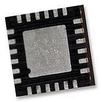
ITG-3200 INVENSENSE, ITG-3200 Datasheet - Page 35

ITG-3200
Manufacturer Part Number
ITG-3200
Description
IC, GYRO, TRI-AXIS, +/-2000 DEG/S
Manufacturer
INVENSENSE
Datasheet
1.ITG-3200.pdf
(39 pages)
Specifications of ITG-3200
No. Of Axes
3
Sensor Case Style
QFN
No. Of Pins
24
Supply Voltage Range
2.1V To 3.6V
Operating Temperature Range
-40°C To +85°C
Interface
I2C, Serial
Interface Type
I2C, Serial
Rohs Compliant
Yes
Lead Free Status / RoHS Status
Lead free / RoHS Compliant
Available stocks
Company
Part Number
Manufacturer
Quantity
Price
Part Number:
ITG-3200
Manufacturer:
INVENSE
Quantity:
20 000
9.10
MEMS (Micro Electro-Mechanical Systems) are a time-proven, robust technology used in hundreds of millions of
consumer, automotive and industrial products. MEMS devices consist of microscopic moving mechanical structures.
They differ from conventional IC products even though they can be found in similar packages. Therefore, MEMS
devices require different handling precautions than conventional ICs prior to mounting onto printed circuit boards
(PCBs).
The ITG-3200 gyroscope has a shock tolerance of 10,000g. InvenSense packages its gyroscopes as it deems proper for
protection against normal handling and shipping. It recommends the following handling precautions to prevent potential
damage.
9.11 Gyroscope Surface Mount Guidelines
Any material used in the surface mount assembly process of the MEMS gyroscope should be free of restricted RoHS
elements or compounds. Pb-free solders should be used for assembly.
In order to assure gyroscope performance, several industry standard guidelines need to be considered for surface
mounting. These guidelines are for both printed circuit board (PCB) design and surface mount assembly and are
available from packaging and assembly houses.
When using MEMS gyroscope components in plastic packages, package stress due to PCB mounting and assembly
could affect the output offset and its value over a wide range of temperatures. This is caused by the mismatch between
the Coefficient Temperature Expansion (CTE) of the package material and the PCB. Care must be taken to avoid
package stress due to mounting.
9.12 Reflow Specification
The approved solder reflow curve shown in the figure below conforms to IPC/JEDEC J-STD-020D.01
(Moisture/Reflow Sensitivity Classification for Nonhermetic Solid State Surface Mount Devices) with a maximum peak
temperature (Tc = 260°C). This is specified for component-supplier reliability qualification testing using lead-free
solder for package thicknesses less than 1.6 mm. The reliability qualification pre-conditioning used by InvenSense
incorporates three of these conforming reflow cycles. All temperatures refer to the topside of the QFN package, as
measured on the package body surface. Customer solder-reflow processes should use the solder manufacturer’s
recommendations, making sure to never exceed the constraints listed in the table and figure below, as these represent
the maximum tolerable ratings for the device. For optimum results, production solder reflow processes should use
lower temperatures, reduced exposure times to high temperatures, and lower ramp-up and ramp-down rates than those
listed below.
Individually packaged or trays of gyroscopes should not be dropped onto hard surfaces. Components placed in trays
could be subject to g-forces in excess of 10,000g if dropped.
Printed circuit boards that incorporate mounted gyroscopes should not be separated by manually snapping apart.
This could also create g-forces in excess of 10,000g.
MEMS Handling Instructions
ITG-3200 Product Specification
Document Number: PS-ITG-3200A-00-01.4
Revision: 1.4
Release Date: 03/30/2010
35 of 39


