MBB02070D4072BCT00 Vishay, MBB02070D4072BCT00 Datasheet - Page 3
MBB02070D4072BCT00
Manufacturer Part Number
MBB02070D4072BCT00
Description
MBB/SMA 0207-25 0.1% CT 40K7
Manufacturer
Vishay
Type
Thin Filmr
Datasheet
1.MBB02070D4072BCT00.pdf
(10 pages)
Specifications of MBB02070D4072BCT00
Power Rating(s)
2/5W
Resistance
40.7kohm
Tolerance (+ Or -)
0.1%
Temperature Coefficient
±25
Termination Style
Axial
Operating Temp Range
-55C to 125C
Case Style
Conformal
Failure Rate
Not Required
Lead Spacing (nom)
Not Requiredmm
Product Length (mm)
6.3mm
Product Depth (mm)
Not Requiredmm
Product Height (mm)
Not Requiredmm
Construction
Cylindrical
Lead Free Status / Rohs Status
Compliant


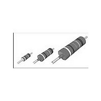
MBA/SMA 0204, MBB/SMA 0207, MBE/SMA 0414 - Precision
Vishay Beyschlag
MBB/SMA 0207 WITH RADIAL TAPING
LEAD SPACING (Variant S = UB) 2.5 mm, SIZE 0207
LEAD SPACING (Variant N = RB) 5.0 mm, SIZE 0207
Area “Z”
www.vishay.com
74
L
H
H
L
H
1
2 ± 0.5
C
C
P
P
1
P
P
2
1
2
P
F
Direction of Unreeling
0
P
F
0
D
P
H
0
P
1.0 + 0.4
1
Direction of Unreeling
d
1.5 ± 0.5
D
Δh
0
3 max.
Δh
“Z”
t
Insulated
For technical questions, contact:
Insulated
H
t
3 ± 1
W
0
3 max.
2
W
W
Precision Thin Film Leaded Resistors
W
2
0
0
16 ± 0.5
W
W
1
1
W
W
1 max.
1 max.
Δh
Δh
1
1
filmresistorsleaded@vishay.com
Notes
(1)
(2)
(3)
DIMENSIONS in millimeters
Lead Ø
Pitch of components
Pitch of sprocket holes
Distance between hole
center and lead center
Distance between hole
center and resistor center
Lead Spacing
Angle of insertion
Angle of insertion
Width of carrier tape
Width of adhesive tape
Position of holes
Position of adhesive tape
Body to hole center
Hole Ø
Thickness of tape
Height for cutting
Height for bending
Height for insertion
DIMENSIONS in millimeters
Lead Ø
Pitch of components
Tape pitch
Distance between hole
center and lead center
Distance between hole
center and resistor center
Lead spacing
Angle of insertion
Angle of insertion
Width of carrier tape
Width of adhesive tape
Position of holes
Position of adhesive tape
Body to hole center
Lead crimp to hole
center
Hole Ø
Thickness of tape
Height for cutting
Height for bending
Height for insertion
Test over 10 holes - 9 intervals P
Parallelism, < 0.5 mm
Thickness of carrier tape: 0.55 mm ± 0.1
(2)
(3)
(3)
(2)
(2)
(1)
Δh1
Δh1
W
W
W
W
W
W
Δh
Δh
P
P
P
D
H
P
P
P
H
D
H
W
W
H
C
H
C
d
P
F
L
d
P
F
L
t
t
0
0
1
2
0
1
0
1
2
0
0
1
0
1
2
0
1
2
12 x 9 = 114.3 ± 0.5
Document Number: 28767
1.3 max.
0.9 max.
1.3 max.
0.9 max.
11 max.
32 max.
11 max.
32 max.
2 max.
2 max.
12.7
12.7
18.0
18.0
12.7
12.7
3.85
6.35
18.0
18.0
16.0
0.6
5.1
5.1
2.5
6.0
9.0
0.5
4.0
2.5
0.6
5.0
6.0
9.0
0.5
4.0
2.5
Revision: 05-Oct-09
+ 0.75, - 0.5
+ 0.75, - 0.5
+ 0.6, - 0.1
+ 0.6, - 0.1
+ 1, - 0.5
+ 0.5, - 0
+ 0, - 0.5
+ 1, - 0.5
+ 0.5, - 0
+ 0, - 0.5
± 2, - 0
+ 2, - 0
TOL.
± 1.0
± 0.3
± 0.7
± 0.7
± 0.5
+ 0.2
TOL.
± 1.0
± 0.3
± 0.7
± 0.7
± 0.5
± 0.5
± 0.2
-
-
-
-
-
-
-
-
-
-
-
-
Related parts for MBB02070D4072BCT00
Image
Part Number
Description
Manufacturer
Datasheet
Request
R

Part Number:
Description:
357-036-542-201 CARDEDGE 36POS DL .156 BLK LOPRO
Manufacturer:
Vishay
Datasheet:
Part Number:
Description:
357-036-542-201 CARDEDGE 36POS DL .156 BLK LOPRO
Manufacturer:
Vishay
Datasheet:
Part Number:
Description:
357-036-542-201 CARDEDGE 36POS DL .156 BLK LOPRO
Manufacturer:
Vishay
Datasheet:
Part Number:
Description:
357-036-542-201 CARDEDGE 36POS DL .156 BLK LOPRO
Manufacturer:
Vishay
Datasheet:
Part Number:
Description:
357-036-542-201 CARDEDGE 36POS DL .156 BLK LOPRO
Manufacturer:
Vishay
Datasheet:
Part Number:
Description:
357-036-542-201 CARDEDGE 36POS DL .156 BLK LOPRO
Manufacturer:
Vishay
Datasheet:
Part Number:
Description:
357-036-542-201 CARDEDGE 36POS DL .156 BLK LOPRO
Manufacturer:
Vishay
Datasheet:
Part Number:
Description:
357-036-542-201 CARDEDGE 36POS DL .156 BLK LOPRO
Manufacturer:
Vishay
Datasheet:
Part Number:
Description:
357-036-542-201 CARDEDGE 36POS DL .156 BLK LOPRO
Manufacturer:
Vishay
Datasheet:
Part Number:
Description:
357-036-542-201 CARDEDGE 36POS DL .156 BLK LOPRO
Manufacturer:
Vishay
Datasheet:
Part Number:
Description:
357-036-542-201 CARDEDGE 36POS DL .156 BLK LOPRO
Manufacturer:
Vishay
Datasheet:
Part Number:
Description:
357-036-542-201 CARDEDGE 36POS DL .156 BLK LOPRO
Manufacturer:
Vishay
Datasheet:
Part Number:
Description:
357-036-542-201 CARDEDGE 36POS DL .156 BLK LOPRO
Manufacturer:
Vishay
Datasheet:
Part Number:
Description:
357-036-542-201 CARDEDGE 36POS DL .156 BLK LOPRO
Manufacturer:
Vishay
Datasheet:
Part Number:
Description:
357-036-542-201 CARDEDGE 36POS DL .156 BLK LOPRO
Manufacturer:
Vishay
Datasheet: