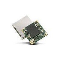
V23993-EVA1084-A VINCOTECH, V23993-EVA1084-A Datasheet - Page 9

V23993-EVA1084-A
Manufacturer Part Number
V23993-EVA1084-A
Description
GPS Modules & Development Tools A1084-B GPS Eval Kit
Manufacturer
VINCOTECH
Type
Evaluation Boardr
Datasheet
1.V23993-EVA1084-A.pdf
(18 pages)
Specifications of V23993-EVA1084-A
Processor Used
A1084
Operating Voltage
5 V
Operating Current
50 mA
Interface Type
USB
Lead Free Status / RoHS Status
Lead free / RoHS Compliant
Lead Free Status / RoHS Status
Lead free / RoHS Compliant
V1.0 – Jan-09
4 On-Board Peripherals
4.1 RESET and ON_OFF Push-Button
The EVA1084-A holds two push-buttons:
• nRST (RESET)
• ON_OFF
The nRST button is used to get a full reset of the GPS module. All parameters are
stored in non-volatile memory. After pushing this button the module starts again
from the beginning.
The ON_OFF button puts the A1084-A GPS receiver into Hibernate state if it is on
and wake up if it is in sleep state. During sleep state the receiver draws 20µA typi-
cally and maintains RTC and SRAM.
Hibernate mode is supported by Firmware version 3.2.5 and later.
4.2 Primary and Auxiliary Antenna Connector
The A1084 -A supports two antenna inputs:
• The antenna connector “Primary Antenna” leads to pin 12 of the A1084-A GPS
• The antenna connector “Auxiliary Antenna” leads to pin 9 of the A1084-A GPS
It can be switched between the two antenna connectors by using the ANT_SW pin
of the A1084-A connected to the DIP switch on board the EVA1084 evaluation kit.
Setting the DIP switch to “ON” means the Auxiliary Antenna input is activated.
Setting the DIP switch to “OFF” means the Primary Antenna input is activated.
receiver which supports passive (and active) GPS antennas.
receiver which supports active GPS antennas.
Figure 6: Primary and Auxiliary Antenna Connector
User’s Manual
Primary Antenna
Auxiliary Antenna
Page 9 of 18


