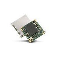
V23993-EVA1084-A VINCOTECH, V23993-EVA1084-A Datasheet - Page 7

V23993-EVA1084-A
Manufacturer Part Number
V23993-EVA1084-A
Description
GPS Modules & Development Tools A1084-B GPS Eval Kit
Manufacturer
VINCOTECH
Type
Evaluation Boardr
Datasheet
1.V23993-EVA1084-A.pdf
(18 pages)
Specifications of V23993-EVA1084-A
Processor Used
A1084
Operating Voltage
5 V
Operating Current
50 mA
Interface Type
USB
Lead Free Status / RoHS Status
Lead free / RoHS Compliant
Lead Free Status / RoHS Status
Lead free / RoHS Compliant
V1.0 – Jan-09
(3) Connect the included active GPS antenna to the Auxiliary Antenna Input of the
(4) To start the GPS Cockpit software which visualizes the NMEA output data com-
(5) Now you need to activate the correct port within GPS Cockpit. You can do this
EVA1084-A and make sure that the antenna has a good view to the sky! Make
sure this input is activated by setting the ANT_SW DIP to the “ON” position.
ing from the GPS receiver, copy all files from the included CD ROM “Tools/GPS
Cockpit” to a folder of you choice on your PC. Then double click the GPSC.exe
file. The GPS cockpit software starts without additional software installation.
by selecting “COM port connection”. A detailed description of the GPS Cockpit
software is included on the CD ROM. In any case, the following window will ap-
pear:
Activate “Terminal 1”, choose the COM port to which the GPS receiver is con-
nected (verify in your system settings - device manager, which communication
port is used for this USB serial connection), in our example COM2 at 4800 baud
(default setting for the EVA1084-A), and click on “OK”:
Figure 3: GPS Cockpit communication window - blank
Figure 2: Disabling of Microsoft Serial BallPoint
Update Driver
Disable
Uninstall
Scan for hardware changes
Properties
User’s Manual
Page 7 of 18


