ST7MDT1-DVP2/US STMicroelectronics, ST7MDT1-DVP2/US Datasheet - Page 67

ST7MDT1-DVP2/US
Manufacturer Part Number
ST7MDT1-DVP2/US
Description
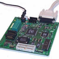
MCU, MPU & DSP Development Tools ST7 Development Kit
Manufacturer
STMicroelectronics
Datasheet
1.ST7MDT1-DVP2US.pdf
(74 pages)
Specifications of ST7MDT1-DVP2/US
Processor To Be Evaluated
ST72254
Interface Type
Parallel Port
Lead Free Status / RoHS Status
Lead free / RoHS Compliant
- Current page: 67 of 74
- Download datasheet (2Mb)
ST7MDT1-DVP2 User Manual
PC (Program Counter)
RC network
SO
STVD7 (ST7 Visual Debug)
Target Device
User Application Board
ZIF Socket
application. The passive probe is connected to the development board by two flat
34-pin cables.
The program counter is the CPU register that holds the address of the next
instruction or operand that the CPU will use.
Resistor-capacitor network.
Small outline. Designates a type of device package with two rows of pins for SMD
or socket mounting.
A graphic debugger software package that allows you to debug applications
destined for the ST7 family of MCUs, either using a built-in simulator function, the
MDT1-DVP Development Kit or an HDS Emulator.
This is the ST7 device that you wish to use in your application, and which the
development kit will emulate for you.
Designates your application board. It should include a socket for inserting the ST7
device or the passive probe.
Zero Insertion Force Socket. This type of programming socket is mounted directly
on the development board. To program an MCU, you insert it into the appropriate
socket (i.e. the SDIP32 ZIF socket for SDIP32 packages, or, if installed, the SO28
ZIF socket for SO28 packages).
Appendix C: Glossary
67/74
Related parts for ST7MDT1-DVP2/US
Image
Part Number
Description
Manufacturer
Datasheet
Request
R

Part Number:
Description:
BOARD PROGRAMMING ST7
Manufacturer:
STMicroelectronics
Datasheet:

Part Number:
Description:
MCU, MPU & DSP Development Tools ST7 Evaluation Board
Manufacturer:
STMicroelectronics

Part Number:
Description:
MCU, MPU & DSP Development Tools ST7 Developmnt Board
Manufacturer:
STMicroelectronics

Part Number:
Description:
MCU, MPU & DSP Development Tools ST7 Emulator Board
Manufacturer:
STMicroelectronics

Part Number:
Description:
STMicroelectronics [RIPPLE-CARRY BINARY COUNTER/DIVIDERS]
Manufacturer:
STMicroelectronics
Datasheet:

Part Number:
Description:
STMicroelectronics [LIQUID-CRYSTAL DISPLAY DRIVERS]
Manufacturer:
STMicroelectronics
Datasheet:

Part Number:
Description:
BOARD EVAL FOR MEMS SENSORS
Manufacturer:
STMicroelectronics
Datasheet:

Part Number:
Description:
NPN TRANSISTOR POWER MODULE
Manufacturer:
STMicroelectronics
Datasheet:

Part Number:
Description:
TURBOSWITCH ULTRA-FAST HIGH VOLTAGE DIODE
Manufacturer:
STMicroelectronics
Datasheet:

Part Number:
Description:
Manufacturer:
STMicroelectronics
Datasheet:

Part Number:
Description:
DIODE / SCR MODULE
Manufacturer:
STMicroelectronics
Datasheet:

Part Number:
Description:
DIODE / SCR MODULE
Manufacturer:
STMicroelectronics
Datasheet:


