GBPC3502-E4/51 Vishay, GBPC3502-E4/51 Datasheet - Page 2
GBPC3502-E4/51
Manufacturer Part Number
GBPC3502-E4/51
Description
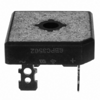
RECTIFIER BRIDGE 35A 200V GBPC
Manufacturer
Vishay
Specifications of GBPC3502-E4/51
Voltage - Peak Reverse (max)
200V
Current - Dc Forward (if)
35A
Diode Type
Single Phase
Speed
Standard Recovery >500ns, > 200mA (Io)
Mounting Type
QC Terminal
Package / Case
GBPC
Product
Single Phase Bridge
Peak Reverse Voltage
200 V
Maximum Rms Reverse Voltage
140 V
Forward Continuous Current
35 A
Max Surge Current
400 A
Forward Voltage Drop
1.1 V
Maximum Reverse Leakage Current
5 uA
Maximum Operating Temperature
+ 150 C
Length
28.8 mm
Width
28.8 mm
Height
7.62 mm
Mounting Style
Through Hole
Minimum Operating Temperature
- 55 C
No. Of Phases
Single
Repetitive Reverse Voltage Vrrm Max
200V
Forward Current If(av)
35A
Forward Voltage Vf Max
1.1V
Diode Mounting Type
Quick Connect
Operating Temperature Range
-55°C To +150°C
Phase Type
Single Phase
Number Of Elements
1
Peak Rep Rev Volt
200V
Rms Voltage (max)
140V
Peak Non-repetitive Surge Current (max)
400A
Avg. Forward Curr (max)
35A
Rev Curr
5uA
Forward Voltage
1.1V
Package Type
Case GBPC
Operating Temp Range
-55C to 150C
Pin Count
4
Mounting
Screw
Operating Temperature Classification
Military
Lead Free Status / RoHS Status
Lead free / RoHS Compliant
Reverse Recovery Time (trr)
-
Lead Free Status / Rohs Status
Compliant
Other names
GBPC3502-E4/1
GBPC3502-E4/1
GBPC3502-E4/1GI
GBPC3502-E4/1GI
GBPC3502-E4/51GI
GBPC3502-E4/1
GBPC3502-E4/1GI
GBPC3502-E4/1GI
GBPC3502-E4/51GI


GBPC12, 15, 25 and 35
Vishay Semiconductors
Electrical Characteristics
Ratings at 25 °C ambient temperature unless otherwise specified.
Thermal Characteristics
Ratings at 25 °C ambient temperature unless otherwise specified.
Notes:
(1) Thermal resistance from junction to case per leg
(2) Bolt down on heatsink with silicone thermal compound between bridge and mounting surface for maximum heat transfer with #10 screw
Ratings and Characteristics Curves
(T
www.vishay.com
2
Maximum instantaneous
forward drop per leg
Maximum reverse DC current at rated DC
blocking voltage per leg
Typical junction capacitance per leg
Typical thermal resistance per leg
A
= 25 °C unless otherwise noted)
40
35
30
25
20
15
10
5
0
0
Figure 1. Maximum Output Rectified Current
60 H
Inductive Load
25
Z
Resistive or
Parameter
50
Case Temperature (°C)
Parameter
75
Bridges Mounted on
9.5 x 3.5 x 4.6"
(22.9 x 8.9 x 11.7 cm)
AL. Finned Plate
100
5 x 6 x 4.9"
AL, Finned Plate
GBPC12
GBPC15
GBPC25
GBPC35
5 x 4 x 3"
AL. Finned Plate
(1)
125
6 x 2.2 x 2.2"
AL. Finned Plate
150
I
I
I
I
T
T
at 4 V, 1 MHz
GBPC12-25
GBPC35
Test condition Symbols
F
F
F
F
A
A
175
= 6.0 A
= 7.5 A
= 12.5 A
= 17.5 A
= 25 °C
= 125 °C
200
Symbols
R
V
C
I
θJC
R
F
J
005
005
40
35
30
25
20
15
10
5
0
Figure 2. Maximum Output Rectified Current
01
01
0
GBPC25
RthS-A = 0.5 °C/W
GBPC15
RthS-A = 1.0 °C/W
GBPC35
RthS-A = 0.5 °C/W
GBPC12
RthS-A = 1.0 °C/W
10
GBPC12, 15, 25, 35
GBPC12, 15, 25, 35
02
02
20
Ambient Temperature (°C)
30
500
300
1.1
5.0
1.9
1.4
04
04
40
50
06
06
60
Document Number 88612
60 H
Inductive Load
70
08
08
Z
Resistive or
80
90 100
10
10
08-Jul-05
°C/W
Units
Units
µA
pF
V
Related parts for GBPC3502-E4/51
Image
Part Number
Description
Manufacturer
Datasheet
Request
R

Part Number:
Description:
RECTIFIER BRIDGE 35A 200V GBPC
Manufacturer:
Vishay
Datasheet:


Part Number:
Description:
GLASS PASSIVATED BRIDGE RECTIFIERS
Manufacturer:
HY Electronic Co., Ltd.
Part Number:
Description:
35A Glass Passivated Bridge Rectifier
Manufacturer:
Taitron Components
Datasheet:
Part Number:
Description:
35A Glass Passivated Bridge Rectifier
Manufacturer:
Taitron Components
Datasheet:
Part Number:
Description:
35A Glass Passivated Bridge Rectifier
Manufacturer:
Taitron Components
Datasheet:
Part Number:
Description:
35A Glass Passivated Bridge Rectifier
Manufacturer:
Taitron Components
Datasheet:
Part Number:
Description:
35A Glass Passivated Bridge Rectifier
Manufacturer:
Taitron Components
Datasheet:
Part Number:
Description:
35A Glass Passivated Bridge Rectifier
Manufacturer:
Taitron Components
Datasheet:
Part Number:
Description:
35A Glass Passivated Bridge Rectifier
Manufacturer:
Taitron Components
Datasheet:
Part Number:
Description:
35A Glass Passivated Bridge Rectifier
Manufacturer:
TAITRON [TAITRON Components Incorporated]
Datasheet:

Part Number:
Description:
357-036-542-201 CARDEDGE 36POS DL .156 BLK LOPRO
Manufacturer:
Vishay
Datasheet:
Part Number:
Description:
357-036-542-201 CARDEDGE 36POS DL .156 BLK LOPRO
Manufacturer:
Vishay
Datasheet:
Part Number:
Description:
357-036-542-201 CARDEDGE 36POS DL .156 BLK LOPRO
Manufacturer:
Vishay
Datasheet: