GBPC3502-E4/51 Vishay, GBPC3502-E4/51 Datasheet

RECTIFIER BRIDGE 35A 200V GBPC

GBPC3502-E4/51

Manufacturer Part Number
GBPC3502-E4/51
Description
RECTIFIER BRIDGE 35A 200V GBPC
Manufacturer
Vishay
Datasheets

Specifications of GBPC3502-E4/51

Voltage - Peak Reverse (max)
200V
Current - Dc Forward (if)
35A
Diode Type
Single Phase
Speed
Standard Recovery >500ns, > 200mA (Io)
Mounting Type
QC Terminal
Package / Case
GBPC
Product
Single Phase Bridge
Peak Reverse Voltage
200 V
Maximum Rms Reverse Voltage
140 V
Forward Continuous Current
35 A
Max Surge Current
400 A
Forward Voltage Drop
1.1 V
Maximum Reverse Leakage Current
5 uA
Maximum Operating Temperature
+ 150 C
Length
28.8 mm
Width
28.8 mm
Height
7.62 mm
Mounting Style
Through Hole
Minimum Operating Temperature
- 55 C
No. Of Phases
Single
Repetitive Reverse Voltage Vrrm Max
200V
Forward Current If(av)
35A
Forward Voltage Vf Max
1.1V
Diode Mounting Type
Quick Connect
Operating Temperature Range
-55°C To +150°C
Phase Type
Single Phase
Number Of Elements
1
Peak Rep Rev Volt
200V
Rms Voltage (max)
140V
Peak Non-repetitive Surge Current (max)
400A
Avg. Forward Curr (max)
35A
Rev Curr
5uA
Forward Voltage
1.1V
Package Type
Case GBPC
Operating Temp Range
-55C to 150C
Pin Count
4
Mounting
Screw
Operating Temperature Classification
Military
Lead Free Status / RoHS Status
Lead free / RoHS Compliant
Reverse Recovery Time (trr)
-
Lead Free Status / Rohs Status
Compliant
Other names
GBPC3502-E4/1
GBPC3502-E4/1
GBPC3502-E4/1GI
GBPC3502-E4/1GI
GBPC3502-E4/51GI
Glass Passivated Single-Phase Bridge Rectifier
Major Ratings and Characteristics
Features
Typical Applications
General purpose use in ac-to-dc bridge full wave rec-
tification for Power Supply, Home Appliances, Office
Equipment, Industrial Automation applications
Maximum Ratings
Ratings at 25 °C ambient temperature unless otherwise specified.
Document Number 88612
08-Jul-05
• UL Recognition file number E54214
• Universal 3-way terminals: snap-on, wire wrap-
• Typical I
• High surge current capability
• Low thermal resistance
• Solder Dip 260 °C, 40 seconds
Maximum repetitive peak reverse voltage
Maximum RMS voltage
Maximum DC blocking voltage
Maximum average forward rectified output
current (See Fig.1)
Peak forward surge current single sine-
wave superimposed on rated load
Rating (non-repetitive, for t greater than
1 ms and less than 8.3 ms) for fusing
RMS isolation voltage from case to leads
Operating junction storage temperature range
around, or P.C.B. mounting
T
V
I
j
I
F(AV)
R
FSM
RRM
V
max.
I
R
F
less than 0.3 µA
Parameter
200 A, 300 A, 300 A, 400 A
12 A, 15 A, 25 A, 35 A
50 V to 1000 V
GBPC12
GBPC15
GBPC25
GBPC35
GBPC12
GBPC15
GBPC25
GBPC35
GBPC12
GBPC15
GBPC25
GBPC35
150 °C
1.1 V
5 µA
Symbols
T
J
V
V
I
V
V
I
F(AV)
, T
FSM
RRM
RMS
I
ISO
DC
2
t
STG
Mechanical Data
Case: GBPC, GBPC-W
Epoxy meets UL-94V-0 Flammability rating
Terminals: Nickel plated on faston lugs or Silver
plated on wire leads (E4 Suffix), solderable per
J-STD-002B and JESD22-B102D. Suffix letter "W"
added to indicate wire leads
GBPC12005W)
Polarity: As marked, Positive lead by belevled corner
Mounting Torque: 20 inches-lbs. max.
005
50
35
50
GBPC12, 15, 25 and 35
GBPC-W
100
100
01
70
GBPC12, 15, 25, 35
200
140
200
02
~
- 55 to + 150
2500
~
400
280
400
200
300
300
400
160
375
375
660
04
12
15
25
35
Vishay Semiconductors
~
600
420
600
06
~
800
560
800
~
GBPC
08
~
www.vishay.com
1000
1000
700
10
A
Units
2
°C
(e.g.
V
V
V
A
A
V
sec
1

Related parts for GBPC3502-E4/51

GBPC3502-E4/51 Summary of contents

Page 1

... RMS V 50 100 DC GBPC12 I F(AV) GBPC15 GBPC25 GBPC35 GBPC12 I FSM GBPC15 GBPC25 GBPC35 GBPC12 GBPC15 GBPC25 GBPC35 V ISO STG Vishay Semiconductors GBPC ~ ~ ~ ~ ~ ~ GBPC12, 15, 25, 35 Units 200 400 600 800 1000 140 280 420 560 700 200 400 600 800 1000 12 15 ...

Page 2

... GBPC12, 15, 25 and 35 Vishay Semiconductors Electrical Characteristics Ratings at 25 °C ambient temperature unless otherwise specified. Parameter Maximum instantaneous GBPC12 forward drop per leg GBPC15 GBPC25 GBPC35 Maximum reverse DC current at rated DC blocking voltage per leg Typical junction capacitance per leg Thermal Characteristics Ratings at 25 ° ...

Page 3

... J J GBPC35 GBPC15 GBPC25 100 50 100 Z Figure 7. Typical Junction Capacitance Per Leg 1,000 100 10 1 1.4 1.6 0.01 Figure 8. Typical Transient Thermal Impedance Per Leg Vishay Semiconductors T = 125 ° 150 ° 400 V 600 - 1000 ° Percent of Rated Peak Reverse Voltage (%) ° ...

Page 4

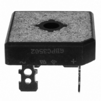
... GBPC12, 15, 25 and 35 Vishay Semiconductors Package outline dimensions in inches (millimeters) GBPC-W 1.135 (28.8) Hole for 1.115 (28.3) #10 Screw 0.220 (5.59) DIA. 0.732 (18.6) 0.200 (5.08) 0.692 (17.6) 1.135 (28.8) 1.115 (28.3) 0.24 (6.0) 0.470 (11.9) 0.18 (4.6) 0.430 (10.9) 0.042 (1.07) ...

Related keywords