PIC-MT Olimex Ltd., PIC-MT Datasheet
PIC-MT
Manufacturer Part Number
PIC-MT
Description
MCU, MPU & DSP Development Tools DEV BRD FOR 28 PIN MICRO CONT
Manufacturer
Olimex Ltd.
Datasheet
1.PIC-MT.pdf
(3 pages)
Specifications of PIC-MT
Processor To Be Evaluated
PIC MCUs
Interface Type
RS-232, ICSP
Dimensions
4.7 in x 1.4 in
Operating Supply Voltage
5 V
Lead Free Status / RoHS Status
Lead free / RoHS Compliant
Available stocks
Company
Part Number
Manufacturer
Quantity
Price
Company:

Part Number:
PIC-MT
Manufacturer:
Olimex Ltd.
Quantity:
135


Features:
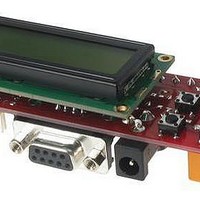
PIC-MT (mini terminal) is development board
for 28 pin PIC microcontrollers with following
features:
To program PIC-MT you need serial port or
parallel port PIC programmers with ICSP
connector (PIC-PG1, PIC-PG3B) or PIC-ICD1-
B.
The serial port ICSP programmer (PIC-PG1)
works with IC PROG ICPROG software,
by Bonny Gijzen. T
may
http://www.icprog.com
The parallel port ICSP programmer (PIC-PG3B)
works with Bojan Dobaj’s shareware software
from
Goodwin’s
www.lpilsley.uklinux.net
ICD/ICSP connector layout:
The ICD/ICSP connector is 6 pin with 0,1" step.
The PIN.1 is marked with square pad on bottom
and arrow on top. ICSP signals are: 1- MCLR, 2-
VDD, 3- VSS/GND, 4- PGD/RB7, 5- PGC/RB6,
6- PGM/RB3.
Development boards for PIC, AVR and MSP430 microcontrollers
Programming:
- ICSP 6 pin connector
- LCD 16x1 alphanumeric display
- 6 buttons
- Dallas iButton interface
- Frequency input
- ADC input
- RS232 interface and connector
- RS232 TTL level interface and connector
- status LED
- relay with 5A/250VAC contacts
- screw terminal blocks on relay contacts
- Audio buzzer
- 4MHz quartz oscillator
- DIL28 microcontroller socket
- +5V power supply voltage regulator
- power supply plug in connector
- dimensions: 120x36 mm
- four mounting holes
be
http://www.picallw.com
download
free
he latest release of ICPROG
PIC-MT (Rev. A) DEVELOPMENT BOARD
FOR 28 PIN PIC MICROCONTROLLERS
software
Copyright(c) 2002, OLIMEX Ltd., All rights reserved.
for
free
or
written
Nigel
from
from
RS232 interface connection:
Rx – RC7, Tx – RC6
LCD connection:
LCD is connected for 4-bit interface
RS - LCD register select RA2
R/W – LCD read write select RA3
E - LCD enable RA5
D4 – RC0
D5 – RC1
D6 – RC2
D7 – RC3
Sample demo program how to drive the LCD is
available on Olimex’s site.
RS232 interface connection:
Microcontroller connection: Rx – RC7, Tx –
RC6
TTL connector: PIN.1 (square) –Tx, PIN.2 –Rx,
PIN.3 – GND, PIN.4 – VCC.
RS232 connector: PIN.2 – Tx, PIN.3 – Rx, PIN.5
– GND.
Dallas iButton interface:
Connected to PB5 via protection circuit.
Dallas connector: PIN.1 (square) – Dallas input,
PIN.2 – GND.
Buttons connection:
The Button interface uses three microcontroller
ports RB0, RB1, RB2. The ports are connected
with pull down resistors and are read as “0”. To
scan the buttons user should set one of the ports
in “1” and to check the other two ports.
For example: set port RB0 as output RB1, RB2
as inputs and make RB0= 1. If buttons B1 is
pressed RB1 will be “1” too, if button B6 is
pressed RB2 will be “1” too. The same way you
can scan all other buttons.
http://www.olimex.com/dev
Related parts for PIC-MT
Image
Part Number
Description
Manufacturer
Datasheet
Request
R

Part Number:
Description:
MCU, MPU & DSP Development Tools MPLAB 8/18/28/40P FOR PICSTART+
Manufacturer:
Olimex Ltd.

Part Number:
Description:
MCU, MPU & DSP Development Tools PROTOTYPE BRD FOR 40 PIN PIC
Manufacturer:
Olimex Ltd.
Datasheet:

Part Number:
Description:
MCU, MPU & DSP Development Tools PROTOTYPE BRD ICSP/ ICD ENABLED 28 PIN
Manufacturer:
Olimex Ltd.
Datasheet:

Part Number:
Description:
MCU, MPU & DSP Development Tools PROTOTYPE BRD ICSP/ ICD ENABLED 14 PIN
Manufacturer:
Olimex Ltd.
Datasheet:

Part Number:
Description:
MCU, MPU & DSP Development Tools PROTOTYPE BRD FOR 28 PIN PIC
Manufacturer:
Olimex Ltd.
Datasheet:

Part Number:
Description:
Development Boards & Kits - PIC / DSPIC MINI PROTOTYPE BRD FOR 8 PIN PIC
Manufacturer:
Olimex Ltd.

Part Number:
Description:
MCU, MPU & DSP Development Tools TCP-IP DEV BRD FOR PIC18F67J60
Manufacturer:
Olimex Ltd.
Datasheet:

Part Number:
Description:
MCU, MPU & DSP Development Tools PROTOTYPE BRD ICSP/ ICD ENABLED 40 PIN
Manufacturer:
Olimex Ltd.
Datasheet:

Part Number:
Description:
MCU, MPU & DSP Development Tools DEV BRD W/GSM MOD PIC18F97J60-I/PT
Manufacturer:
Olimex Ltd.
Datasheet:

Part Number:
Description:
MCU, MPU & DSP Development Tools PROTOTYPE BRD FOR PIC18F67J60
Manufacturer:
Olimex Ltd.
Datasheet:

Part Number:
Description:
Microcontroller & Microprocessor Development Tools TCP-IP DEV BRD PIC32MX460F512
Manufacturer:
Olimex Ltd.
Datasheet:

Part Number:
Description:
Microcontroller & Microprocessor Development Tools PROTOTYPE BOARD TMS320F28027
Manufacturer:
Olimex Ltd.
Datasheet:

Part Number:
Description:
Microcontroller & Microprocessor Development Tools HDR BRD FOR LPC3131
Manufacturer:
Olimex Ltd.
Datasheet:

Part Number:
Description:
Microcontroller & Microprocessor Development Tools MP3 PLYR MOD WITH VS1002
Manufacturer:
Olimex Ltd.
Datasheet:
Part Number:
Description:
Microcontroller & Microprocessor Development Tools MP3 PLYR MOD BAT WITH VS1002
Manufacturer:
Olimex Ltd.
Datasheet:
PIC-MT Summary of contents
Page 1
... Programming: To program PIC-MT you need serial port or parallel port PIC programmers with ICSP connector (PIC-PG1, PIC-PG3B) or PIC-ICD1- B. The serial port ICSP programmer (PIC-PG1) works with IC PROG ICPROG software, he latest release of ICPROG by Bonny Gijzen ...
Page 2
... Connected to RA0. Input voltage may be 0-5V between PIN.2 and PIN.3 (GND) or 0-10V between PIN.1 and PIN.3. Board component locations: Frequency input: Connected to RA4 (TOCKI). Supported devices: All PIC 28 pin microcontrollers. Power supply: The power supply should be in range +10 +14VDC. Ordering codes: PIC-MT - assembled and tested ...
Page 3
...