HFBR-0566 Avago Technologies US Inc., HFBR-0566 Datasheet - Page 14
HFBR-0566
Manufacturer Part Number
HFBR-0566
Description
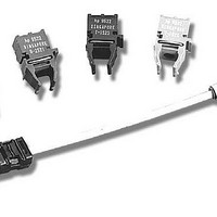
Fiber Optic Development Tools MT-RJ 622Mb/s Fast E Evaluation Kit
Manufacturer
Avago Technologies US Inc.
Datasheet
1.HFBR-0566.pdf
(17 pages)
Specifications of HFBR-0566
Description/function
Fiber Optic Kit
For Use With/related Products
HFBR-5908E, HFCT-5908E
Lead Free Status / RoHS Status
Lead free / RoHS Compliant


HFBR-5908E
Transmitter Optical Characteristics
(T
Receiver Optical Characteristics
(T
Notes:
1. Over temperatures, voltage and lifetime for 50µm and 62.5 µm fiber.
2. The relationship between FWHM and RMS values for spectral width can be derived from the assumption of a Gaussian shaped spectrum which
3. These are unfiltered 20-80% values.
4. This specification is intended to indicate the performance of the receiver section of the transceiver when the input power ranges from the mini-
14
Parameter
Receiver Sensitivity
Input Optical Power Maximum
Input Operating Wavelength
Signal Detect - Asserted
Signal Detect - Deasserted
Signal Detect - Hysteresis
Parameter
Output Optical Power
Optical Extinction Ratio
Center Wavelength
Spectral Width - rms
Optical Rise/Fall Time
Overshoot
A
A
results in RMS = FWHM/2.35.
mum level (with a window time-width) to the maximum level. Over this range the receiver is guaranteed to provide output data with a Bit Error
Ratio (BER) better than or equal to 1 x 10
• At the Beginning of Life (BOL)
• Over the specified operating temperature and voltage ranges
• Input is at 622.08 Mbd, 2
• Receiver worst-case output data eye-opening (window time-width) is measured by applying worst-case input systematic (SJ) and random
• Transmitter operating with a 622.08 MBd, 311.04 MHz square wave input signal to simulate any cross talk present between the transmitter
= 0°C to +70°C, V
= 0°C to +70°C, V
Appendix 1.
jitter (RJ). The worst-case maximum input SJ = 0.5 ns peak-to-peak and the RJ = 0.15 ns peak-to-peak per ANSI T1.646a standard. Since the
random jitter contribution is very small and difficult to produce exactly, only the maximum systematic jitter is produced and used for testing
the receiver. The corresponding receiver test window time-width must meet the requirement of 0.31 ns or larger. This worst-case test
window time-width results from the following jitter equation:
Minimum Test Window Time-Width = Baud Interval - Tx SJ max. - Rx SJ max. - Rx RJ max.
Respectively, Minimum Test Window Time-Width = 1.608 ns - 0.50 ns - 0.30 ns - 0.48 ns = 0.328 ns.
This is a test method that is within practical test error of the worst-case 0.31 ns limit.
and receiver sections of the transceiver.
CC
CC
23
= 3.14 V to 3.47 V)
= 3.14 V to 3.47 V)
-1 PRBS data pattern with 72 “1”s and 72 “0”s inserted per the CCITT (now ITU-T) recommendation G.958
-10
Symbol
P
P
l
P
P
P
Symbol
P
l
s
t
r
A
A
IN MIN
IN MAX
D
OUT
C
/t
- P
f
D
Min.
-14
1270
-42
1
Min.
-20.0
10
1270
Typ.
-30
-7
P
-34.5
2
Typ.
0
D
+2 dB
Max.
-26
1380
-31
3
Max.
-14
1380
2.5
1.25
25
Unit
dBm avg.
dBm avg. 4
nm
dBm avg.
dBm avg.
dB
Unit
dBm avg. 1
dB
nm
nm rms
ns
%
Reference
Reference
2
3
Related parts for HFBR-0566
Image
Part Number
Description
Manufacturer
Datasheet
Request
R

Part Number:
Description:
Fiber Optic Transmitters, Receivers, Transceivers 1300nm 155MBd 16-pin DIP ST Rx
Manufacturer:
Avago Technologies US Inc.

Part Number:
Description:
FIBER OPTIC TX 125 MBD 650N
Manufacturer:
Avago Technologies US Inc.
Datasheet:

Part Number:
Description:
Fiber Optic Evaluation Kit
Manufacturer:
Avago Technologies US Inc.
Datasheet:

Part Number:
Description:
RECEIVER FIBER OPTIC ST 266MBD
Manufacturer:
Avago Technologies US Inc.
Datasheet:

Part Number:
Description:
RCVR OPT HI SPEED VERS LINK HORZ
Manufacturer:
Avago Technologies US Inc.
Datasheet:

Part Number:
Description:
RCVR OPT HI SPEED VERS LINK VERT
Manufacturer:
Avago Technologies US Inc.
Datasheet:

Part Number:
Description:
TXRX OPTICAL 850NM VCSEL MT-RJ
Manufacturer:
Avago Technologies US Inc.
Datasheet:

Part Number:
Description:
TXRX MM SFP LC CONN BAIL DELATCH
Manufacturer:
Avago Technologies US Inc.
Datasheet:

Part Number:
Description:
TXRX MMF SFP GBE/FC BAIL DELATCH
Manufacturer:
Avago Technologies US Inc.
Datasheet:

Part Number:
Description:
XMITTER FIBER OPTIC 266MBD ST
Manufacturer:
Avago Technologies US Inc.
Datasheet:

Part Number:
Description:
OPTOCOUPLER GATE DRV 2A 16-SOIC
Manufacturer:
Avago Technologies US Inc.
Datasheet:
Part Number:
Description:
OPTOCOUPLER 2CH 2.5A 16-SOIC
Manufacturer:
Avago Technologies US Inc.
Datasheet:

Part Number:
Description:
OPTOCOUPLER GATE DRV 0.4A 16SOIC
Manufacturer:
Avago Technologies US Inc.
Datasheet:

Part Number:
Description:
OPTOCOUPLER 2.0A 250KHZ 8-DIP
Manufacturer:
Avago Technologies US Inc.
Datasheet:

Part Number:
Description:
OPTOCOUPLER 2.0A 250KHZ GW 8-SMD
Manufacturer:
Avago Technologies US Inc.
Datasheet: