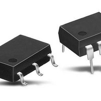
AQW614E Panasonic, AQW614E Datasheet - Page 3

AQW614E
Manufacturer Part Number
AQW614E
Description
Solid State Relays 100MA 400V 1FORMA / 1FORMB
Manufacturer
Panasonic
Datasheet
1.AQW614A.pdf
(3 pages)
Specifications of AQW614E
Control Voltage Range
1.5 V to 5 V
Load Voltage Rating
400 V
Load Current Rating
100 mA
Contact Form
1 Form A, 1 Form B
Output Device
MOSFET
Mounting Style
SMD/SMT
Relay Type
PhotoMOS
Turn-on Switching
Instantaneous
Package / Case
DIP-8
Termination Style
Solder Pad
Lead Free Status / RoHS Status
Lead free / RoHS Compliant
Available stocks
Company
Part Number
Manufacturer
Quantity
Price
Company:
Part Number:
AQW614E
Manufacturer:
Panasonic Electric Works
Quantity:
135
Company:
Part Number:
AQW614EH
Manufacturer:
NXP
Quantity:
5 400
Company:
Part Number:
AQW614EH
Manufacturer:
NAIS
Quantity:
5 539
Part Number:
AQW614EH
Manufacturer:
NAIS
Quantity:
20 000
4. Reverse time vs. ambient temperature
characteristics
LED current: 5 mA; Load voltage: 400 V (DC);
Continuous load current: 100 mA (DC)
7. LED dropout voltage vs. ambient
temperature characteristics
LED current: 5 to 50 mA
10. Operate time vs. LED forward current
characteristics
Measured portion: between terminals 5 and 6, 7 and 8;
Load voltage: 400 V (DC); Continuous load current:
100 mA (DC); Ambient temperature: 25°C
1.5
1.4
1.3
1.2
1.1
1.0
3.0
2.5
2.0
1.5
1.0
0.5
1.2
1.0
0.8
0.6
0.4
0.2
0
0
0
–40
–40
10
–20
–20
Ambient temperature, °C
Ambient temperature, °C
20
LED forward current, mA
Between terminal 5 and 6 (N.O.)
Between terminal 7 and 8 (N.C.)
0
Between terminal 5 and 6 (N.O.)
Between terminal 7 and 8 (N.C.)
0
20
30
20
40
40
40
60
60
50
All Rights Reserved © COPYRIGHT Panasonic Electric Works Co., Ltd.
77°F
8085
8085
50mA
30mA
20mA
10mA
5mA
60
5. LED operate current vs. ambient
temperature characteristics
Load voltage: 400 V (DC);
Continuous load current: 100 mA (DC)
8. Current vs. voltage characteristics of output
at MOS portion
Measured portion: between terminals 5 and 6, 7 and 8;
Ambient temperature: 25°C
11. Reverse time vs. LED forward current
characteristics
Measured portion: between terminals 5 and 6, 7 and 8;
Load voltage: 400 V (DC); Continuous load current:
100 mA (DC); Ambient temperature: 25°C
0.6
0.5
0.4
0.3
0.2
0.1
6
5
4
3
2
1
0
0
–40
–5
–4
10
10
–20
–3
LED forward current, mA
–2
20
20
Ambient temperature, °C
Between terminal 5 and 6 (N.O.)
Between terminal 7 and 8 (N.C.)
Between terminal 5 and 6 (N.O.)
Between terminal 7 and 8 (N.C.)
0
–1
100
80
60
40
20
20
30
30
77°F
Between terminal
7 and 8
(N.C.)
–20
–40
–60
–80
–100
1 2 3 4 5
40
40
40
Voltage, V
Between terminal
5 and 6 (N.O.)
60
50
50
77°F
8085
60
60
GU Form A & B (AQW614)
6. LED reverse current vs. ambient
temperature characteristics
Load voltage: 400 V (DC);
Continuous load current: 100 mA (DC)
9. Off state leakage current vs. load voltage
characteristics
Measured portion: between terminals 5 and 6, 7 and 8;
Ambient temperature: 25°C
12. Output capacitance vs. applied voltage
characteristics
Measured portion: between terminals 5 and 6, 7 and 8;
Frequency: 1 MHz;
Ambient temperature: 25°C
120
100
10
80
60
40
20
10
10
10
0
6
5
4
3
2
1
0
–12
–3
–6
–9
0
–40
10
Between terminal 7 and 8 (N.C.)
Between terminal 5 and 6 (N.O.)
–20
20
20
Ambient temperature, °C
Between terminal 5 and 6 (N.O.)
Between terminal 7 and 8 (N.C.)
Between terminal 5 and 6 (N.O.)
Between terminal 7 and 8 (N.C.)
0
Applied voltage, V
Load voltage, V
40
30
20
77°F
77°F
60
40
40
60
80
50
8085
60
100


