103185-7 TE Connectivity, 103185-7 Datasheet - Page 35
103185-7
Manufacturer Part Number
103185-7
Description
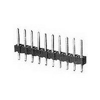
07 MODII HDR SRST B/A .100CL
Manufacturer
TE Connectivity
Type
Unshrouded Headerr
Datasheet
1.103185-7.pdf
(139 pages)
Specifications of 103185-7
Pitch (mm)
2.54mm
Gender
HDR
Number Of Contacts
7POS
Number Of Contact Rows
1
Mounting Style
Through Hole
Body Orientation
Straight
Contact Plating
Gold Over Nickel
Operating Temp Range
-65C to 105C
Termination Method
Solder
Current Rating (max)
3/ContactA
Contact Material
Phosphor Bronze
Housing Material
Thermoplastic
Housing Color
Black
Product Height (mm)
8.13mm
Product Length (mm)
17.37mm
Product Depth (mm)
2.34mm
Rohs Compliant
NO
Product Type
Connector
Mount Angle
Vertical
Pcb Mount Retention
Without
Surface Mount Compatible
No
Board Standoff
Without
Mounting Ears
Without
Mating Connector Lock
Without
Post Size (mm [in])
0.64 [.025]
Mating Post Length (mm [in])
5.84 [0.230]
Panel Mount Retention
Without
Current Rating (a)
3
Insulation Resistance (m?)
5,000
Dielectric Withstanding Voltage (v)
750
Termination Post Length (mm [in])
3.05 [0.120]
Solder Tail Contact Plating
Tin-Lead over Nickel
Header Type
Breakaway
Number Of Positions
7
Centerline (mm [in])
2.54 [0.100]
Row-to-row Spacing (mm [in])
2.54 [0.100]
Number Of Rows
1
Selectively Loaded
No
Mount Type
Printed Circuit Board
Contact Plating, Mating Area, Material
Gold (15)
Contact Shape
Square
Contact Base Material
Phosphor Bronze
Ul Flammability Rating
UL 94V-0
Rohs/elv Compliance
ELV compliant, 5 of 6 Compliant
Lead Free Solder Processes
Wave solder capable to 240°C
Approved Standards
UL E28476, CSA LR7189
Operating Temperature (°c)
-65 – +105
High Temperature Housing
No
High Speed Serial Data Connector
No
Lead Free Status / RoHS Status
Not Compliant


5
118
.025 [0.64] Square
Straight Posts
Material and Finish:
Housing—Black thermoplastic, 94V-0
rated, high temperature compatible
P o s t s—Phosphor bronze, plated as
f o l l o w s :
Plating A—Duplex plated .000030
[0.00076] gold on contact area, .000100-
.000200 [0.00254-0.00508] tin-lead on
solder tail, with entire post underplated
.000050 [0.00127] nickel
Plating B—Duplex plated .000015
[0.00038] gold on contact area, .000100-
.000200 [0.00254-0.00508] tin-lead on
solder tail, with entire post underplated
.000050 [0.00127] nickel
Plating C— . 0 0 0 1 0 0 - . 0 0 0 2 0 0
[0.00254-0.00508] tin-lead over
.000050 [0.00127] nickel
Performance Characteristics
(Board Retention Tails):
Insertion Force—12 lb [53.4N] Max.
Retention Force—.25 lb [1.11N] Min.
Related Product Data:
Mateable Connectors—Refer
to the Mating Post Selection Guide
(page 89)
Technical Documents
See mating connector for applicable
product and application specifications.
Notes: 1. Headers without retention tails may be broken to the desired number of positions using Tool Kit No. 314818-1 (not shown).
Notes:
Notes:
Notes: 3.
Catalog 1307819
Catalog 1307819
Revised 6-04
Revised 6-04
www.tycoelectronics.com
www.tycoelectronics.com
Retention Tails
Solder Tails
(See Notes
(See Notes
With Board
Header
1 and 2.)
2 and 3.)
Style
W i t h
2. Headers are also available in sizes 2 thru 39 positions (with Solder Tails) and 4 thru 39 positions (with Board Retention Tails).
3. For C dimensions .120 [3.05] and .125 [3.18], board retention using kinked tails are for headers 6 positions and smaller; headers
When ordering, add the prefix and/or suffix (dash) numbers to the base part number that corresponds with the desired size.
For example, the complete part number for an 8-position header with solder tails (C dimension .090 [2.29], post plating A) would
be 146285-8. The complete part number for a 26-position header with board retention tails (C dimension .120 [3.05], post
plating B) would be 2-146292-6. This part numbering system applies only to this page.
7 positions and larger use swaged tails. Headers with a C dimension of .090 [2.29] have swaged tails for all sizes.
No. of
Pos.
4 0
4 0
1
3
(page 294):
Dimensions are in inches and
Dimensions are in inches and
millimeters unless otherwise
millimeters unless otherwise
specified. Values in brackets
specified. Values in brackets
are metric equivalents.
are metric equivalents.
3.984 [ 1 0 1 . 1 9 ]
3.984 [ 1 0 1 . 1 9 ]
.084 [ 2 . 1 3 ]
.284 [ 7 . 2 1 ]
A
Dimensions
AMPMODU Interconnection System
Breakaway Surface-Mount Compatible, High Temperature Headers—Unshrouded,
S i n g l e - R o w, .100 [2.54] Centerline with Special Stand-offs
Headers with Board Retention Tails
Headers with Solder Tails
3.900 [ 9 9 . 0 6 ]
3.900 [ 9 9 . 0 6 ]
Recommended Hole Size
.200 [ 5 . 0 8 ]
Recommended Hole Size
[0.89±0.08]
[1.14±0.02]
[1.02±0.08]
[1.14±0.02]
.035±.003
.045±.001
—
B
.040±.003
.045±.001
Before Plating
Before Plating
(Plated)
(Plated)
*±.003 [±0.08] tolerances not to accumulate within one connector pattern.
4 - 1 4 6 2 8 5 - 0
4 - 1 4 6 2 9 7 - 0
*±.003 [±0.08] tolerances not to accumulate within one connector pattern.
Dia. Typ.
Dia. Typ.
Plating A
1 4 6 2 8 5 - 1
1 4 6 2 9 7 - 3
Dia. Typ.
Dia. Typ.
Post Plating/Part Nos.
Dimensions are shown for
Dimensions are shown for
reference purposes only.
reference purposes only.
Specifications subject
Specifications subject
to change.
to change.
[0.64]
[0.64]
(for .062 [1.57] thick PC board; .008 [.203] thick stencil)
(for .062 [1.57] thick PC board; .008 [.203] thick stencil)
.025
Typ.
.025
Typ.
C = .090 [2.29]
D = .230 [5.84]
E = .185 [4.70]
[2.54]
[2.54]
.100*
.100*
4 - 1 4 6 2 8 4 - 0
4 - 1 4 6 2 9 6 - 0
Plating B
1 4 6 2 8 4 - 1
1 4 6 2 9 6 - 3
Recommended PC Board Mounting Pattern
Recommended PC Board Mounting Pattern
4 - 1 4 6 2 8 2 - 0
4 - 1 4 6 2 9 4 - 0
Plating C
1 4 6 2 8 2 - 1
1 4 6 2 9 4 - 3
Plating A
4 - 1 4 6 2 8 1 - 0
4 - 1 4 6 2 9 3 - 0
1 4 6 2 8 1 - 1
1 4 6 2 9 3 - 3
USA: 1-800-522-6752
USA: 1-800-522-6752
Canada: 1-905-470-4425
Canada: 1-905-470-4425
Mexico: 01-800-733-8926
Mexico: 01-800-733-8926
C. America: 52-55-5-729-0425
C. America: 52-55-5-729-0425
B
B
A
A
B
B
Post Plating/Part Nos.
[0.76±0.05]
.030±.002
[0.76±0.05]
.030±.002
C = .120 [3.05]
D = .230 [5.84]
E = .185 [4.70]
4 - 1 4 6 2 8 0 - 0
4 - 1 4 6 2 9 2 - 0
Plating B
1 4 6 2 8 0 - 1
1 4 6 2 9 2 - 3
Plating C
4 - 1 4 6 2 7 8 - 0
4 - 1 4 6 2 9 0 - 0
1 4 6 2 7 8 - 1
1 4 6 2 9 0 - 3
[1.14]
.045
Typ.
[1.14]
.045
Typ.
[2.29±0.05]
C
.090±.002
note 3)
(see
C
4 - 1 4 6 2 7 7 - 0
4 - 1 4 6 2 8 9 - 0
Plating A
1 4 6 2 7 7 - 1
1 4 6 2 8 9 - 3
South America: 55-11-3611-1514
South America: 55-11-3611-1514
Hong Kong: 852-2735-1628
Hong Kong: 852-2735-1628
Japan: 81-44-844-8013
Japan: 81-44-844-8013
UK: 44-141-810-8967
UK: 44-141-810-8967
D
Post Plating/Part Nos.
D
[3.81±0.05]
.150±.002
C = .125 [3.18]
D = .318 [8.08]
E = .200 [5.08]
Plating B
4 - 1 4 6 2 7 6 - 0
4 - 1 4 6 2 8 8 - 0
1 4 6 2 7 6 - 1
1 4 6 2 8 8 - 3
(Contact Area)
(Contact Area)
E Ref.
E Ref.
Plating C
4 - 1 4 6 2 7 4 - 0
4 - 1 4 6 2 8 6 - 0
1 4 6 2 7 4 - 1
1 4 6 2 8 6 - 3
[2.29]
[2.29]
.090
.090
Related parts for 103185-7
Image
Part Number
Description
Manufacturer
Datasheet
Request
R

Part Number:
Description:
Conn Unshrouded Header HDR 3 POS 2.54mm Solder ST Thru-Hole
Manufacturer:
TE Connectivity
Datasheet:
Part Number:
Description:
Conn Unshrouded Header HDR 1 POS Solder ST Thru-Hole
Manufacturer:
TE Connectivity
Datasheet:
Part Number:
Description:
Conn Unshrouded Header HDR 2 POS 2.54mm Solder ST Thru-Hole
Manufacturer:
TE Connectivity
Datasheet:
Part Number:
Description:
Conn Unshrouded Header HDR 4 POS 2.54mm Solder ST Thru-Hole
Manufacturer:
TE Connectivity
Datasheet:
Part Number:
Description:
Conn Unshrouded Header HDR 6 POS 2.54mm Solder ST Thru-Hole
Manufacturer:
TE Connectivity
Datasheet:

Part Number:
Description:
High Speed / Modular Connectors 30P HEADER ASSY
Manufacturer:
TE Connectivity
Datasheet:

Part Number:
Description:
High Speed / Modular Connectors REC 6X005P R/A LT B-PLANE HS3
Manufacturer:
TE Connectivity
Datasheet:

Part Number:
Description:
High Speed / Modular Connectors 2MM HM RCPT 50P R/A AU
Manufacturer:
TE Connectivity
Datasheet:

Part Number:
Description:
High Speed / Modular Connectors 2MM HM RCPT 50P R/A AU
Manufacturer:
TE Connectivity
Datasheet:


Part Number:
Description:
Manufacturer:
TE Connectivity
Datasheet:


Part Number:
Description:
Manufacturer:
TE Connectivity
Datasheet:

Part Number:
Description:
Manufacturer:
TE Connectivity
Datasheet:

Part Number:
Description:
Manufacturer:
TE Connectivity
Datasheet: