103185-7 TE Connectivity, 103185-7 Datasheet - Page 108
103185-7
Manufacturer Part Number
103185-7
Description
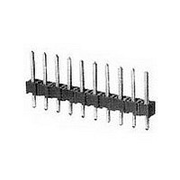
07 MODII HDR SRST B/A .100CL
Manufacturer
TE Connectivity
Type
Unshrouded Headerr
Datasheet
1.103185-7.pdf
(139 pages)
Specifications of 103185-7
Pitch (mm)
2.54mm
Gender
HDR
Number Of Contacts
7POS
Number Of Contact Rows
1
Mounting Style
Through Hole
Body Orientation
Straight
Contact Plating
Gold Over Nickel
Operating Temp Range
-65C to 105C
Termination Method
Solder
Current Rating (max)
3/ContactA
Contact Material
Phosphor Bronze
Housing Material
Thermoplastic
Housing Color
Black
Product Height (mm)
8.13mm
Product Length (mm)
17.37mm
Product Depth (mm)
2.34mm
Rohs Compliant
NO
Product Type
Connector
Mount Angle
Vertical
Pcb Mount Retention
Without
Surface Mount Compatible
No
Board Standoff
Without
Mounting Ears
Without
Mating Connector Lock
Without
Post Size (mm [in])
0.64 [.025]
Mating Post Length (mm [in])
5.84 [0.230]
Panel Mount Retention
Without
Current Rating (a)
3
Insulation Resistance (m?)
5,000
Dielectric Withstanding Voltage (v)
750
Termination Post Length (mm [in])
3.05 [0.120]
Solder Tail Contact Plating
Tin-Lead over Nickel
Header Type
Breakaway
Number Of Positions
7
Centerline (mm [in])
2.54 [0.100]
Row-to-row Spacing (mm [in])
2.54 [0.100]
Number Of Rows
1
Selectively Loaded
No
Mount Type
Printed Circuit Board
Contact Plating, Mating Area, Material
Gold (15)
Contact Shape
Square
Contact Base Material
Phosphor Bronze
Ul Flammability Rating
UL 94V-0
Rohs/elv Compliance
ELV compliant, 5 of 6 Compliant
Lead Free Solder Processes
Wave solder capable to 240°C
Approved Standards
UL E28476, CSA LR7189
Operating Temperature (°c)
-65 – +105
High Temperature Housing
No
High Speed Serial Data Connector
No
Lead Free Status / RoHS Status
Not Compliant


Product Facts
Performance
Characteristics
Mechanical Characteristics:
Mating Force—8.0 oz. [2.22N] per
contact (max.)
Unmating Force—.75 oz. [0.28N] per
contact (min.)
Durability (Tested to)—200 cycles
Environmental Characteristics:
Operating Temperature—
-65°C to +105°C
Catalog 1307819
Catalog 1307819
Catalog 1307819
Revised 6-04
Revised 6-04
Revised 6-04
www.tycoelectronics.com
www.tycoelectronics.com
www.tycoelectronics.com
Dual-cantilever beam
contact with box design
Single-row assemblies
have .100 [2.54] centerline
contact spacing; double-row
assemblies have .100 x .100
[2.54 x 2.54] centerline
contact spacing
3 through 40 positions in
single-row assemblies;
2 through 80 positions in
double-row assemblies
Mod II Standard .340 [8.64]
and Mod IV low
.265 [6.73] profiles
Mod II and Mod IV profiles
available in dual entry
Duplex gold and bright tin-
lead plated contacts have
full nickel underplate
Thermoplastic housings,
94V-0 rated
Standoffs for easy flux
cleaning
All throughhole assemblies
are end stackable
Recognized under the
Component Program of
Underwriters
Laboratories Inc.,
File No. E28476
Certified by Canadian
Standards
Association,
File No. LR 7189
Dimensions are in inches and
Dimensions are in inches and
Dimensions are in inches and
millimeters unless otherwise
millimeters unless otherwise
millimeters unless otherwise
specified. Values in brackets
specified. Values in brackets
specified. Values in brackets
are metric equivalents.
are metric equivalents.
are metric equivalents.
Electrical Characteristics:
Current Rating—3.0 amperes (max.)
for single contact; 2.0 amperes (max.)
per contact when connector is fully
energized
Contact Resistance—12 milliohms
(max.)
Insulation Resistance—5000
megohms (min.) between adjacent
contacts
Dielectric Withstanding Voltage
(at sea level)—750 V rms
AMPMODU Interconnection System
Receptacle Assemblies, Vertical Mount
Vertical receptacle
assemblies are designed to
reliably and economically
meet the packaging and
interconnection
requirements of today’s
electronic industry.
This broad product line
offers a wide variety of
assembly styles and
features. They are
available in dual entry style,
in both single and double
row configurations. The
.100 [2.54] centerline
assemblies are available in
Dimensions are shown for
Dimensions are shown for
Dimensions are shown for
reference purposes only.
reference purposes only.
reference purposes only.
Specifications subject
Specifications subject
Specifications subject
to change.
to change.
to change.
3-40 (single row) positions
and 2-80 (double row)
positions. Standard and
low profile housings which
are end stackable also
enhance the product line
giving the advantage of
added flexibility.
The housings are made of
flame retardant material
that is 94 V-0 rated.
Contacts are phosphor
bronze, fully underplated
with nickel to help prevent
corrosion and are available
in three plating options.
USA: 1-800-522-6752
USA: 1-800-522-6752
USA: 1-800-522-6752
Canada: 1-905-470-4425
Canada: 1-905-470-4425
Canada: 1-905-470-4425
Mexico: 01-800-733-8926
Mexico: 01-800-733-8926
Mexico: 01-800-733-8926
C. America: 52-55-5-729-0425
C. America: 52-55-5-729-0425
C. America: 52-55-5-729-0425
The receptacle contact is
an established proven
design, with a fully
enclosed one-piece “box”
to protect the contact
beams.
These assemblies are
offered in .265 [6.73]
(Mod IV) and .340[8.64]
(Mod II) high profiles.
Standard solder tails
accommodate board
thickness of .062 [1.57].
Product styles include
single and dual tine
variations. Outrigger tine
styles are also available
for bottom entry parallel
board stacking
applications.
South America: 55-11-3611-1514
South America: 55-11-3611-1514
South America: 55-11-3611-1514
Hong Kong: 852-2735-1628
Hong Kong: 852-2735-1628
Hong Kong: 852-2735-1628
Japan: 81-44-844-8013
Japan: 81-44-844-8013
Japan: 81-44-844-8013
UK: 44-141-810-8967
UK: 44-141-810-8967
UK: 44-141-810-8967
191
5
Related parts for 103185-7
Image
Part Number
Description
Manufacturer
Datasheet
Request
R

Part Number:
Description:
Conn Unshrouded Header HDR 3 POS 2.54mm Solder ST Thru-Hole
Manufacturer:
TE Connectivity
Datasheet:
Part Number:
Description:
Conn Unshrouded Header HDR 1 POS Solder ST Thru-Hole
Manufacturer:
TE Connectivity
Datasheet:
Part Number:
Description:
Conn Unshrouded Header HDR 2 POS 2.54mm Solder ST Thru-Hole
Manufacturer:
TE Connectivity
Datasheet:
Part Number:
Description:
Conn Unshrouded Header HDR 4 POS 2.54mm Solder ST Thru-Hole
Manufacturer:
TE Connectivity
Datasheet:
Part Number:
Description:
Conn Unshrouded Header HDR 6 POS 2.54mm Solder ST Thru-Hole
Manufacturer:
TE Connectivity
Datasheet:

Part Number:
Description:
High Speed / Modular Connectors 30P HEADER ASSY
Manufacturer:
TE Connectivity
Datasheet:

Part Number:
Description:
High Speed / Modular Connectors REC 6X005P R/A LT B-PLANE HS3
Manufacturer:
TE Connectivity
Datasheet:

Part Number:
Description:
High Speed / Modular Connectors 2MM HM RCPT 50P R/A AU
Manufacturer:
TE Connectivity
Datasheet:

Part Number:
Description:
High Speed / Modular Connectors 2MM HM RCPT 50P R/A AU
Manufacturer:
TE Connectivity
Datasheet:


Part Number:
Description:
Manufacturer:
TE Connectivity
Datasheet:


Part Number:
Description:
Manufacturer:
TE Connectivity
Datasheet:

Part Number:
Description:
Manufacturer:
TE Connectivity
Datasheet:

Part Number:
Description:
Manufacturer:
TE Connectivity
Datasheet: