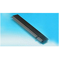
7-5530843-5 TE Connectivity, 7-5530843-5 Datasheet - Page 8

7-5530843-5
Manufacturer Part Number
7-5530843-5
Description
CONN SEC II 6 POS 100C/L
Manufacturer
TE Connectivity
Type
Card Edger
Datasheet
1.7-5530843-5.pdf
(15 pages)
Specifications of 7-5530843-5
Number Of Contacts
12POS
Number Of Contact Rows
2
Body Orientation
Straight
Contact Plating
Gold Over Nickel
Contact Material
Phosphor Bronze
Termination Method
Solder
Mounting Style
Through Hole
Product Height (mm)
15.49mm
Operating Temp Range
-55C to 85C
Pitch (mm)
2.54mm
Housing Material
Polyester
Housing Color
Black
Current Rating (max)
3/ContactA
Voltage Rating Max
400VAC
Contact Resistance Max
10
Rohs Compliant
YES
Product Type
Connector
Product Series
Standard Edge II
Type Of Connector
Standard
Number Of Dual Positions
6
Post Type
Solder Post
Pcb Mounting Orientation
Vertical
Mounting Ears
Without
Pcb Mount Retention
Without
High Current
No
Termination Post Length (mm [in])
3.18 [0.125]
Solder Tail Contact Plating
Tin
Centerline (mm [in])
2.54 [0.100]
Retention Latch
Without
Positions Unloaded
None
Contact Plating, Mating Area, Material
Gold (30)
Contact Base Material
Phosphor Bronze
Underplate Material
Nickel
Ul Flammability Rating
UL 94V-0
Rohs/elv Compliance
RoHS compliant, ELV compliant
Lead Free Solder Processes
Wave solder capable to 240°C, Wave solder capable to 260°C, Wave solder capable to 265°C
Rohs/elv Compliance History
Always was RoHS compliant
Lead Free Status / RoHS Status
Compliant
180
Design Notes
Mating PCB Requirements
Mating PCB edge fingers should be gold plated, have
.050" (1.3 mm) side margins, and be of suitable copper
weight for power applications. Mating board thickness is
.062 [1.60].
Sequenced Mating
Sequenced mating can be achieved by designing one or
more setback traces on the mating card edge, or by
notching the edge of the card.
End-to-end Mounting
CROWN EDGE modules can be placed end-to-end for
connector assemblies up to 8" (203.20 mm) long.
Mating PC Card Edge Samples
The drawings below show two PC card edge samples with
signal and power lines designed to mate with 2 and 3-
segment CROWN EDGE modules.
Hot-Plug Requirements
Hot-plug application of this product requires the use of the
CROWN EDGE true hot-plug modules (see part numbers
on pages 177-179) mated with a customer-supplied metal
blade or bus bar. Dimensions of a sample mating blade for
use with CROWN EDGE hot-plug modules is shown below.
Catalog 1773096
Revised 2-10
www.tycoelectronics.com
Sequenced Power Traces and 30 Signal Traces
2 x 2 Segment Modules Provide Two
Dimensions are in inches and
millimeters unless otherwise
specified. Values in brackets
are metric equivalents.
Power Connectors & Interconnection Systems
CROWN EDGE Card Edge-style High Current Connectors
Dimensions are shown for
reference purposes only.
Specifications subject
to change.
Chamfer
Mating Edges
USA: 1-800-522-6752
Canada: 1-905-470-4425
Mexico: 01-800-733-8926
C. America: 52-55-1106-0803
Ground Plane and 12 Signal Lines
2 x 3 Segment Modules Provide
South America: 55-11-2103-6000
Hong Kong: 852-2735-1628
Japan: 81-44-844-8013
UK: 44-(0)8002-67666
(Continued)


