91500-1 TE Connectivity, 91500-1 Datasheet - Page 2
91500-1
Manufacturer Part Number
91500-1
Description
TOOLS,CRIMP,RATCHET,CERTICRIMP 2,SAHT UMNL20-14,CABLE WRAP,CERTI-CRIMP II STRAIGHT AND CERTI-CRIMP DOUBLE ACTION HAND TOOLS ,TYCO ELECTRONICS / AMP
Manufacturer
TE Connectivity
Type
Toolr
Specifications of 91500-1
Rohs Compliant
NA
Application
Universal MATE-N-LOK® II connectors
Diameter, Insulation
0.060-0.130 in.
Tool Type
Crimp Tool
Wire Range
20-14 AWG
Wire Size
20-14 AWG
Lead Free Status / RoHS Status
RoHS Not Applicable


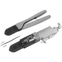
2. DESCRIPTION
The FRONT of the tool, is marked with the tool part
number, wire size ranges, and crimp height
specifications.
The tool features a fixed die (crimper), a movable die
(anvil), a locator/insulation stop, and a ratchet. Many
tools feature an insulation adjustment knob which is
used to regulate the crimp height of the contact
insulation barrel during the crimping operation. The
locator/insulation stop positions the contact, and limits
the insertion distance of the stripped wire into the
contact. In use, the locator/insulation stop rests in the
locator slot of the contact (See Figures 1 and 2). The
ratchet assures full crimping of the contact. Once
Cumulative Trauma Disorders can result from the prolonged use of manually powered hand tools. Hand tools are intended for occasional use and low volume
applications. A wide selection of powered application equipment for extended- - use, production operations is available.
DNOTE: Some tools do not have insulation adjustment knobs.
These tools are fixed at one position with a spring pin.
2 of 4
DInsulation
Adjustment
Knob
(Shown in
Position 1)
Locator/
Insulation
Stop
Insulation
Crimper
Stripped
Wire
Typical Socket
Contact
Front
of Tool
Figure 1
Mating
Portion
1
Wire Barrel
Typical
Pin Contact
Wire
Crimper
Wire
Anvil
Terminal
Support
PROPER USE GUIDELINES
Insulation
Anvil
Figure 2
Locator
Slot
Insulation
Barrel
engaged, the ratchet will not release until the dies have
been fully closed.
3. CRIMPING PROCEDURE
Refer to the table at http://tooling.tycoelectronics.com to
ensure that the wire intended for use is compatible with
the wire size and insulation diameter specified in the
table. Strip the wire to the length indicated in the table.
Proceed as follows:
Insulation Adjustment Procedure
On many tools, the insulation barrel crimp height is
regulated by the insulation adjustment knob
(Figure 1). The insulation crimp should hold the
insulation firmly without cutting into the insulation.
To determine the proper insulation crimp setting, test
CAUTION
1. Hold the tool so that the FRONT side is facing you.
2. Ensure that the tool ratchet is released by
squeezing the tool handles and allowing them to open
FULLY.
3. Holding the contact by its mating portion and
looking straight into the crimp section, insert the
contact from the BACK of the tool into the appropriate
crimp chamber.
4. Position the contact between the crimpers so that
the locator/insulation stop enters the slot in the
contact. The wire barrel should butt against the
locator/insulation stop. Refer to Figures 1 and 2.
5. Holding the contact in this position, squeeze the
tool handles together until the insulation anvil starts
entry into the insulation crimper (usually two ratchet
clicks). Do NOT deform the insulation barrel or wire
barrel.
6. Insert a properly stripped wire through the locator
slot and into the wire barrel of the contact until the
insulation butts against the locator/insulation stop.
7. Holding wire in place, crimp contact to the wire by
squeezing the tool handles together until the ratchet
releases.
8. Allow tool handles to open FULLY and remove the
crimped contact from the tool.
Do NOT cut or nick the wire strands during wire
stripping.
Wire Strip
Length
Note: Not to Scale
408- 8547
Rev F
Related parts for 91500-1
Image
Part Number
Description
Manufacturer
Datasheet
Request
R

Part Number:
Description:
Printers THERMAL PRINTER HS-SLEEVE MARKER
Manufacturer:
TE Connectivity


Part Number:
Description:
High Speed / Modular Connectors 30P HEADER ASSY
Manufacturer:
TE Connectivity
Datasheet:

Part Number:
Description:
High Speed / Modular Connectors REC 6X005P R/A LT B-PLANE HS3
Manufacturer:
TE Connectivity
Datasheet:

Part Number:
Description:
High Speed / Modular Connectors 2MM HM RCPT 50P R/A AU
Manufacturer:
TE Connectivity
Datasheet:

Part Number:
Description:
High Speed / Modular Connectors 2MM HM RCPT 50P R/A AU
Manufacturer:
TE Connectivity
Datasheet:


Part Number:
Description:
Manufacturer:
TE Connectivity
Datasheet:


Part Number:
Description:
Manufacturer:
TE Connectivity
Datasheet:

Part Number:
Description:
Manufacturer:
TE Connectivity
Datasheet:

Part Number:
Description:
Manufacturer:
TE Connectivity
Datasheet: