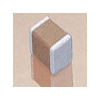
08055E104ZAT2A AVX Corporation, 08055E104ZAT2A Datasheet - Page 9

08055E104ZAT2A
Manufacturer Part Number
08055E104ZAT2A
Description
CAPACITOR CERAMIC, 0.1UF, 50V, Z5U, 0805
Manufacturer
AVX Corporation
Series
0805r
Specifications of 08055E104ZAT2A
Tolerance (+ Or -)
-20% to 80%
Voltage
50VDC
Temp Coeff (dielectric)
Z5U
Operating Temp Range
10C to 85C
Mounting Style
Surface Mount
Construction
SMT Chip
Case Style
Ceramic Chip
Failure Rate
Not Required
Wire Form
Not Required
Product Length (mm)
2.01mm
Product Depth (mm)
1.25mm
Product Height (mm)
1.3mm
Product Diameter (mm)
Not Requiredmm
Capacitance
.1uF
Package / Case
0805
Dielectric Characteristic
Z5U
Capacitance Tolerance
+80, -20%
Voltage Rating
50VDC
Capacitor Case Style
0805
No. Of Pins
2
Capacitor Mounting
SMD
Rohs Compliant
Yes
Tolerance
- 20 %, 80 %
Operating Temperature Range
+ 10 C to + 85 C
Temperature Coefficient / Code
Z5U
Product
General Type MLCCs
Dimensions
0.049 in W x 0.079 in L x 0.930 mm H
Termination Style
SMD/SMT
Lead Free Status / RoHS Status
Compliant
C0G (NP0) Capacitors for RF/Microwave
Ultra Low ESR, “U” Series, C0G (NP0) Chip Capacitors
GENERAL INFORMATION
“U” Series capacitors are C0G (NP0) chip capacitors spe-
cially designed for “Ultra” low ESR for applications in the
communications market. Max ESR and effective capacitance
HOW TO ORDER
DIMENSIONS:
ELECTRICAL CHARACTERISTICS
Capacitance Values and Tolerances:
Temperature Coefficient of Capacitance (TC):
Insulation Resistance (IR):
Working Voltage (WVDC):
8
Case Size
B
0805
Size
0402
0603
0805
1210
0402
0603
0805
1210
Size 0402 - 0.2 pF to 15 pF @ 1 MHz
Size 0603 - 1.0 pF to 47 pF @ 1 MHz
Size 0805 - 1.6 pF to 160 pF @ 1 MHz
Size 1210 - 2.4 pF to 1000 pF @ 1 MHz
0 ± 30 ppm/°C (-55° to +125°C)
10
10
Size
0402 -
0603 -
0805 -
1210 -
A
0402
12
11
Ω min. @ 25°C and rated WVDC
Ω min. @ 125°C and rated WVDC
0.039 ± 0.004 (1.00 ± 0.10) 0.020 ± 0.004 (0.50 ± 0.10)
0.060 ± 0.010 (1.52 ± 0.25) 0.030 ± 0.010 (0.76 ± 0.25)
0.079 ± 0.008 (2.01 ± 0.20) 0.049 ± 0.008 (1.25 ± 0.20) 0.040 ± 0.005 (1.02 ± 0.127) 0.020 ± 0.010 (0.51 ± 0.255)
0.126 ± 0.008 (3.2 ± 0.20)
C
Working Voltage
25 WVDC
200, 100, 50 WVDC
200, 100 WVDC
200, 100 WVDC
Voltage
3 = 25V
5 = 50V
1 = 100V
2 = 200V
Code
1
inches (millimeters)
A
Dielectric =
Ultra Low
B
D
ESR
U
EIA Capacitance Code in pF.
First two digits = significant figures
or “R” for decimal place.
Third digit = number of zeros or after
“R” significant figures.
0.098 ± 0.008 (2.49 ± 0.20) 0.050 ± 0.005 (1.27 ± 0.127) 0.025 ± 0.015 (0.635 ± 0.381) 0.040 (1.02) min.
E
A
0603
D
Capacitance
C
B
100
Capacitance
M = ±20%
Tolerance
C = ±0.25 pF
D = ±0.5 pF
G = ±2%
B = ±0.1 pF
K = ±10%
F = ±1%
J = ±5%
Code
B
J
D
0.024 (0.60) max.
0.036 (0.91) max.
are met on each value producing lot to lot uniformity.
Sizes available are EIA chip sizes 0603, 0805, and 1210.
Dielectric Working Voltage (DWV):
Equivalent Series Resistance Typical (ESR):
Marking:
MILITARY SPECIFICATIONS
A
E
0805
D
C
Failure Rate
250% of rated WVDC
0402 -
0603 -
0805 -
1210 -
Meets or exceeds the requirements of MIL-C-55681
Applicable
C
A = Not
Code
A
Laser marking EIA J marking standard
(except 0603) (capacitance code and
tolerance upon request).
See Performance Curve, page 9
See Performance Curve, page 9
See Performance Curve, page 9
See Performance Curve, page 9
0.010 ± 0.005 (0.25 ± 0.13)
Termination
T= Plated Ni
and Solder
T
B
N/A
D
D
Packaging
2 = 7" Reel
4 = 13" Reel
9 = Bulk
A
E
Code
1210
2
D
C
0.030 (0.76) min.
0.020 (0.51) min.
inches (mm)
A = Standard
N/A
Special
E
Code
A


