ADNS-6010 Avago Technologies US Inc., ADNS-6010 Datasheet - Page 9
ADNS-6010
Manufacturer Part Number
ADNS-6010
Description
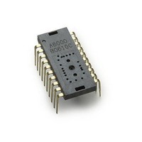
Optical Sensors - Board Mount Laser mouse sensor
Manufacturer
Avago Technologies US Inc.
Datasheet
1.ADNS-6010.pdf
(41 pages)
Specifications of ADNS-6010
Lead Free Status / RoHS Status
Lead free / RoHS Compliant
Available stocks
Company
Part Number
Manufacturer
Quantity
Price


LASER Drive Mode
The LASER has 2 modes of operation: DC and Shutter. In
DC mode, the LASER is on at all times the chip is powered
except when in the power down mode via the NPD pin.
In shutter mode the LASER is on only during the portion
of the frame that light is required. The LASER mode is set
by the LASER_MODE bit in the Configuration_bits regis-
ter. For optimum product lifetime, Avago Technologies
recommends the default Shutter mode setting (except
for calibration and test).
Laser Bin Table
Eye Safety
The ADNS-6010 and the associated components in the
schematic of Figure 7 are intended to comply with Class
1 Eye Safety Requirements of IEC 60825-1. Avago Tech-
nologies suggests that manufacturers perform testing to
verify eye safety on each mouse. It is also recommended
to review possible single fault mechanisms beyond those
described below in the section “Single Fault Detection”.
Under normal conditions, the ADNS-6010 generates the
drive current for the laser diode (ADNV-6340). In order to
stay below the Class 1 power requirements, resistor Rbin
must be set at least as high as the value in the bin table
of Figure 7, based on the bin number of the laser diode
and LP_CFG0 and LP_CFG1 must be programmed to ap-
propriate values. Avago Technologies recommends using
the exact Rbin value specified in the bin table to ensure
sufficient laser power for navigation. The system com-
prised of the ADNS-6010 and ADNV-6340 is designed to
maintain the output beam power within Class 1 require-
ments over component manufacturing tolerances and
the recommended temperature range when adjusted per
the procedure below and when implemented as shown
in the recommended application circuit of Figure 7. For
more information, please refer to Avago Technologies La-
ser Mouse Eye Safety Calculation Application Note 5088.
9
Bin Number
2A
3A
Parameter
Laser output power
Rbin Resistor
Value (kohm)
18.7
12.7
Symbol
LOP
Match_Bit
(Reg 0x2C, Bit7)
0
0
Minimum
Maximum
716
LASER Power Adjustment Procedure
1. The ambient temperature should be 25C +/- 5C.
2. Set VDD3 to its permanent value.
3. Ensure that the laser drive is at 100% duty cycle.
4. Program the LP_CFG0 and LP_CFG1 registers to
Good engineering practices should be used to guarantee
performance, reliability and safety for the product design.
Avago Technologies has additional information and de-
tail, such as firmware practices, PCB layout suggestions,
and manufacturing procedures and specifications that
could be provided.
LASER Output Power
The laser beam output power as measured at the navi-
gation surface plane is specified below. The following
conditions apply:
1. The system is adjusted according to the above
2. The system is operated within the recommended
3. The VDD3 value is no greater than 50mV above its
4. No allowance for optical power meter accuracy is
Disabling the LASER
LASER_NEN is connected to the base of a PNP transistor
which when ON connects V
operation, LASER_NEN is low. In the case of a fault con-
dition (ground at XY_LASER or RBIN), LASER_NEN goes
high to turn the transistor off and disconnect V
the LASER.
achieve an output power as close to 506uW as
possible without exceeding it.
procedure.
operating temperature range.
value at the time of adjustment.
assumed.
Units
uW
Notes
Per conditions above
DD3
to the LASER. In normal
DD3
from
Related parts for ADNS-6010
Image
Part Number
Description
Manufacturer
Datasheet
Request
R

Part Number:
Description:
Optical Mouse Sensor,DIP
Manufacturer:
Avago Technologies US Inc.
Datasheet:

Part Number:
Description:
Optical Mouse Sensor,DIP
Manufacturer:
Avago Technologies US Inc.
Datasheet:

Part Number:
Description:
Trim Lens For ADNS-3530
Manufacturer:
Avago Technologies US Inc.
Datasheet:

Part Number:
Description:
8 DIP SFF Navigation Sensor
Manufacturer:
Avago Technologies US Inc.
Datasheet:

Part Number:
Description:
Trim Lens For ADNS-5090
Manufacturer:
Avago Technologies US Inc.
Datasheet:

Part Number:
Description:
BLACK CLIP FOR ADNS-5000
Manufacturer:
Avago Technologies US Inc.
Datasheet:
Part Number:
Description:
Lens For ADNS-7630
Manufacturer:
Avago Technologies US Inc.
Datasheet:

Part Number:
Description:
Optical Mouse Sensor,DIP
Manufacturer:
Avago Technologies US Inc.
Datasheet:

Part Number:
Description:
SENSOR OPTICAL MOUSE 8-DIP
Manufacturer:
Avago Technologies US Inc.
Datasheet:
Part Number:
Description:
Optical Mouse Sensor,DIP
Manufacturer:
Avago Technologies US Inc.
Datasheet:

Part Number:
Description:
OPTOCOUPLER GATE DRV 2A 16-SOIC
Manufacturer:
Avago Technologies US Inc.
Datasheet:
Part Number:
Description:
OPTOCOUPLER 2CH 2.5A 16-SOIC
Manufacturer:
Avago Technologies US Inc.
Datasheet:

Part Number:
Description:
OPTOCOUPLER GATE DRV 0.4A 16SOIC
Manufacturer:
Avago Technologies US Inc.
Datasheet:

Part Number:
Description:
OPTOCOUPLER 2.0A 250KHZ 8-DIP
Manufacturer:
Avago Technologies US Inc.
Datasheet:

Part Number:
Description:
OPTOCOUPLER 2.0A 250KHZ GW 8-SMD
Manufacturer:
Avago Technologies US Inc.
Datasheet: