KIT34844AEPEVBE Freescale Semiconductor, KIT34844AEPEVBE Datasheet - Page 18
KIT34844AEPEVBE
Manufacturer Part Number
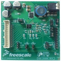
KIT34844AEPEVBE
Description
LED Lighting Development Kits IC, 10 CHANNEL LED BACKLIGHT
Manufacturer
Freescale Semiconductor
Datasheet
1.MC34844AEP.pdf
(62 pages)
Specifications of KIT34844AEPEVBE
Supply Voltage
12 V
Supply Current
2 uA
For Use With/related Products
34844A
Lead Free Status / RoHS Status
Lead free / RoHS Compliant


to the Boost, cycle by cycle of the PWM. It helps the boost to
respond faster every time the load turns back on again.
CURRENT MIRROR
10 LED strings to within 2%. The maximum current is set
using a resistor to GND from the ISET pin. This can be scaled
down using the I
I
or by pulling PWM pin low regardless of the duty cycle.
individually or in parallel.
converter stops switching.
connecting the LED string to 2 or more LED channels in
parallel. For example; if the application requires to drive 5
channels at 100 mA, then the bottom of each LED string
should be connected to two channels in order to duplicate the
current capability (Example: CH0+CH1 = 100 mA).
PWM GENERATOR
modes, as set by the M/~S pin.
programmed through the I
The default programmed value set the number of 25 kHz
clocks (40 μs) in one PWM cycle. The 18-bit resolution allows
minimum PWM frequencies of 100 Hz to be programmed.
The resulting frequency is output on the CK pin.
digital PLL uses this frequency as the PWM frequency. By
setting one device as master, and connecting the CK output
to the input on a number of slave configured devices, all
PWM frequencies are synchronized together.
slave modes is set using a second register on the I
interface (register DPWM), and can be controlled from 100%
duty cycle to 1/256 T
is achieved by turning LED drivers off (register CHENx = 0h)
or pulling PWM pin low.
'AND'ed with the internal signal. By setting the serial interface
to 100% duty cycle (default), the external pin has full control
of the PWM duty cycle. This pin can also be used to modulate
Analog Integrated Circuit Device Data
Freescale Semiconductor
2
C (registers CHENx = 0 h) for a duty cycle from 0% to 99%
Also the device has a precharge voltage that add 0.5 Volts
The programmable current mirror matches the current in
Zero current is achieved by turning off the LED Driver by
I
In the off state, the LEDs current is set to 0 and the boost
This feature allows to drive more than 50 mA of current by
The PWM generator can operate in either master or slave
In master mode, the internal PWM generator frequency is
In slave mode, the CK pin acts as an input. The internal
The duty cycle of the PWM waveform in both master and
An external PWM can also be used. The PWM input is
2
C capability allows the channels to be controlled
Current on LED Channel (PIN and NIN mode disabled)
PWMFrequency Hz
Current A
2
C interface to 255 levels.
PWM
PWM Frequency
[ ]
[
= 0.39%. Zero percent of duty cycle
=
2
]
C interface (registers FPWM).
ICH RegisterValue
-----------------------------------------------------------
=
------------------------------------------------------------------- -
FPWM RegisterValue
RSET ohms
[
[
[
19.2Mhz
]
]
]
2
C
Eqn. 1
Eqn. 2
the LED at a lower frequency than the PWM dimming
frequency (Minimum pulse width = 150 ns).
interface (STROBE bit = 1). In this mode, each rising edge of
the PWM signal turns on the next channel, while turning off
all other channels. The duration that the channel is
illuminated is set by the duty cycle of the PWM input pin. This
can be used to scan the output channels.
DISABLING LED CHANNELS
the 10 channels separately by writing the corresponding
CHENx bit on Registers 08 and 09 thru I2C.
starts to operate, the corresponding LED driver is disabled
but the feedback circuit is still connected. This may interfere
with the operation of the dynamic headroom control (DHC)
which can lead to erratic output voltage regulation. For this
condition, the output voltage may ramp up to the OVP level if
the voltage on the LED driver is not substantially above the
DHC regulation voltage (0.75 V typ). Because of this
operation under I
connect the unused channels to VDC2 thru a100 kohm
resistor and also follow the below powering up sequence:
channels are being used because the voltage across the LED
drivers is always equal or higher than the DHC regulation
voltage (0.75 V typ). For this condition, the user can disable/
enable any of the channels thru I
erratic behavior but the FAIL pin cannot be cleared. If FAIL
pin is to be cleared thru I
suggested configuration shown at the FAIL PIN session.
FAIL PIN
that particular LED channel will be close to ground and the
LED open failure is detected. When this happens, a failure is
registered, the FAIL pin is set to its high-impedance stage,
and the channel is turned off.
complete power on reset is applied. However for I
mode, the FAIL pin is cleared by disabling the malfunction
channels (CHENx = 0) and clearing the failure bit (CLRFAIL
bit = 1).
floating or unused channels, then the unused channels must
be connected to VDC2 thru a 100 kohm resistor to avoid
reach instability problems. This will allow detecting another
failure from the connected channels. (See
1. PWM pin = Low.
2. Power up the part.
3. Program the I
4. Enable the Boost and current drivers by taking PWM
A pulsed mode can also be programmed using the I
The 34844 allows the user to enable and disable each of
When a channel is disabled thru the I
This previous device's operation does not happen when all
If a LED fails open in any of the LED strings, the voltage in
The FAIL pin cannot be cleared for manual mode unless a
If the application only requires clearing the failure for the
channels.
pin to HIGH.
FUNCTIONAL INTERNAL BLOCK DESCRIPTION
2
C/SMBUS Mode, we recommend to
2
C commands and disable the unused
2
C, it will be necessary to use the
2
FUNCTIONAL DESCRIPTION
C without causing any
2
C prior the device
Figure
2
C/SMBUS
6)
2
34844
C
18
Related parts for KIT34844AEPEVBE
Image
Part Number
Description
Manufacturer
Datasheet
Request
R

Part Number:
Description:
Manufacturer:
Freescale Semiconductor, Inc
Datasheet:
Part Number:
Description:
Manufacturer:
Freescale Semiconductor, Inc
Datasheet:
Part Number:
Description:
Manufacturer:
Freescale Semiconductor, Inc
Datasheet:
Part Number:
Description:
Manufacturer:
Freescale Semiconductor, Inc
Datasheet:
Part Number:
Description:
Manufacturer:
Freescale Semiconductor, Inc
Datasheet:
Part Number:
Description:
Manufacturer:
Freescale Semiconductor, Inc
Datasheet:
Part Number:
Description:
Manufacturer:
Freescale Semiconductor, Inc
Datasheet:
Part Number:
Description:
Manufacturer:
Freescale Semiconductor, Inc
Datasheet:
Part Number:
Description:
Manufacturer:
Freescale Semiconductor, Inc
Datasheet:
Part Number:
Description:
Manufacturer:
Freescale Semiconductor, Inc
Datasheet:
Part Number:
Description:
Manufacturer:
Freescale Semiconductor, Inc
Datasheet:
Part Number:
Description:
Manufacturer:
Freescale Semiconductor, Inc
Datasheet:
Part Number:
Description:
Manufacturer:
Freescale Semiconductor, Inc
Datasheet:
Part Number:
Description:
Manufacturer:
Freescale Semiconductor, Inc
Datasheet:
Part Number:
Description:
Manufacturer:
Freescale Semiconductor, Inc
Datasheet: