PV10-12R-Q Panduit Corp, PV10-12R-Q Datasheet - Page 6
PV10-12R-Q
Manufacturer Part Number
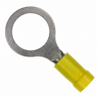
PV10-12R-Q
Description
RING TERMINAL 10-12 AWG
Manufacturer
Panduit Corp
Series
Pan-Term®r
Type
One-Holer
Specifications of PV10-12R-Q
Terminal Type
Circular
Stud/tab Size
1/2 Stud
Thickness
0.040" (1.02mm)
Width - Outer Edges
0.720" (18.29mm)
Length - Overall
1.460" (37.10mm)
Mounting Type
Free Hanging (In-Line)
Termination
Crimp
Wire Gauge
10-12 AWG
Insulation
Insulated
Color
Yellow
Contact Material
Copper
Contact Finish
Tin, 100µin (2.54µm)
Insulation Diameter
0.225" (5.72mm)
Material - Insulation
Vinyl
Angle
Straight
Brand/series
PV10 Series
Contact Plating
Tin
Diameter, Insulation
0.225 "
Insulation Type
Vinyl
Length, Overall
1.46 "
Material, Contact
Copper
Package Quantity
50
Primary Type
Ring
Size, Stud
1⁄2 "
Special Features
Brazed Seam, Barrel
Width, Overall
0.72 "
Wire Size
12-10 AWG
Lead Free Status / RoHS Status
Lead free / RoHS Compliant
Features
-
Lead Free Status / Rohs Status
Lead free / RoHS Compliant
Other names
PV10-12R-L
PV10-12R-L
Q4337443
PV10-12R-L
Q4337443


A6
Crimping Guidelines for PANDUIT
Terminals,Disconnects,Splices and Wire Joints
(continued)
Insulated and Non-Insulated Wire Joints
NOTES for Crimping with the preferred Hand Operated
Controlled Cycle Crimping Tools:
A. Properly strip wires per manufacturer’s recommendations
B. Twist stripped wire ends together, and insert wires into
C. Locate wire joint in appropriate wire gauge crimp die pocket
D. Squeeze tool handles firmly to perform the electrical crimp.
1. PANDUIT controlled cycle crimping tools properly locate rings, forks,
2. When using the preferred controlled cycle tool, once a crimp has been
3. Controlled cycle tools provide the electrical crimp and the insulation
4. When using controlled cycle tooling, insulated butt splices must be
Steps 1 & 2
and barrel insulated disconnects, pins, and blades. No further
positioning is required.
started, the ratchet device of controlled cycle tools will not release until
the crimp is complete, independent of operator expertise.
closure in a single cycle of the tool.
inserted from the back of the tool to ensure that the electrical and
insulation closure crimp pockets are properly aligned with the splice.
on product package label.
wire joint.
and position crimp in the center of the metal insert.
(See Note 2 below)
Note: an insulation crimp is not required on an insulated
wire joint.
Steps 3 & 4
®
P
Complete Crimp
AN
-T
ERM
®
Related parts for PV10-12R-Q
Image
Part Number
Description
Manufacturer
Datasheet
Request
R

Part Number:
Description:
TERM,RING VYL 12-10AWG 1/4
Manufacturer:
Panduit Corp
Datasheet:

Part Number:
Description:
TERM RING VYL 12-10AWG 3/8
Manufacturer:
Panduit Corp
Datasheet:

Part Number:
Description:
TERM,RING VYL 12-10AWG 1/4
Manufacturer:
Panduit Corp
Datasheet:

Part Number:
Description:
TERM RING VYL 12-10AWG #10
Manufacturer:
Panduit Corp
Datasheet:
Part Number:
Description:
TERM RING VYL 12-10AWG #6
Manufacturer:
Panduit Corp
Datasheet:

Part Number:
Description:
NetKey USB 2.0 Female A/Female A Coupler
Manufacturer:
Panduit Corp