PV10-12R-Q Panduit Corp, PV10-12R-Q Datasheet - Page 55
PV10-12R-Q
Manufacturer Part Number
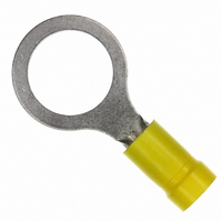
PV10-12R-Q
Description
RING TERMINAL 10-12 AWG
Manufacturer
Panduit Corp
Series
Pan-Term®r
Type
One-Holer
Specifications of PV10-12R-Q
Terminal Type
Circular
Stud/tab Size
1/2 Stud
Thickness
0.040" (1.02mm)
Width - Outer Edges
0.720" (18.29mm)
Length - Overall
1.460" (37.10mm)
Mounting Type
Free Hanging (In-Line)
Termination
Crimp
Wire Gauge
10-12 AWG
Insulation
Insulated
Color
Yellow
Contact Material
Copper
Contact Finish
Tin, 100µin (2.54µm)
Insulation Diameter
0.225" (5.72mm)
Material - Insulation
Vinyl
Angle
Straight
Brand/series
PV10 Series
Contact Plating
Tin
Diameter, Insulation
0.225 "
Insulation Type
Vinyl
Length, Overall
1.46 "
Material, Contact
Copper
Package Quantity
50
Primary Type
Ring
Size, Stud
1⁄2 "
Special Features
Brazed Seam, Barrel
Width, Overall
0.72 "
Wire Size
12-10 AWG
Lead Free Status / RoHS Status
Lead free / RoHS Compliant
Features
-
Lead Free Status / Rohs Status
Lead free / RoHS Compliant
Other names
PV10-12R-L
PV10-12R-L
Q4337443
PV10-12R-L
Q4337443


Crimping Guidelines for PANDUIT
Compression Lugs and Splices (continued)
4. Crimp the connector.
*See condensed tool charts on pages B4-B27; for complete tool charts
refer to pages D2.148-D2.186 of the Electrical Solutions Catalog,
SA-ELCB03, at www.panduit.com.
Insert the conductor into the barrel of the connector. The
conductor should stop against the end of the barrel of the
towards the conductor entry at the
end of the barrel. Use the color coded
or knurled band markings on the
barrel of the connector to evenly
space the placement of the crimps in
the barrel.
When properly crimped, the die index number engraved in the
crimping die will be embossed into the barrel of the connector.
The crimp should be placed in the connector so the die index
number can be easily read when the connector is installed.
Identify
For service and technical support, call 800-777-3300
Die index number must be visible
or visit www.panduit.com.
lug, or wire stop in the butt splice, upon
complete insertion of the conductor
in the barrel. Some lugs are offered
with inspection windows that provide
visual inspection of the complete
conductor insertion.
Review the installation instructions
included with the PANDUIT product
packaging or the tool charts* for the
proper number of crimps to be placed
in the connector. Make the first crimp in
the barrel nearest the tongue of the lug,
or wire stop in a butt splice, and make
successive crimps in the barrel working
®
P
AN
-L
UG
™
B3
Related parts for PV10-12R-Q
Image
Part Number
Description
Manufacturer
Datasheet
Request
R

Part Number:
Description:
TERM,RING VYL 12-10AWG 1/4
Manufacturer:
Panduit Corp
Datasheet:

Part Number:
Description:
TERM RING VYL 12-10AWG 3/8
Manufacturer:
Panduit Corp
Datasheet:

Part Number:
Description:
TERM,RING VYL 12-10AWG 1/4
Manufacturer:
Panduit Corp
Datasheet:

Part Number:
Description:
TERM RING VYL 12-10AWG #10
Manufacturer:
Panduit Corp
Datasheet:
Part Number:
Description:
TERM RING VYL 12-10AWG #6
Manufacturer:
Panduit Corp
Datasheet:

Part Number:
Description:
NetKey USB 2.0 Female A/Female A Coupler
Manufacturer:
Panduit Corp