VK202-25-USB Matrix Orbital, VK202-25-USB Datasheet - Page 18
VK202-25-USB
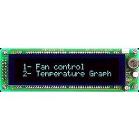
Manufacturer Part Number
VK202-25-USB
Description
Vacuum Fluorescent Displays (VFD) Vacuum Florescent Blue/Green Text
Manufacturer
Matrix Orbital
Datasheet
1.VK202-25-USB.pdf
(57 pages)
Specifications of VK202-25-USB
Lead Free Status / Rohs Status
Lead free / RoHS Compliant


3.3 The display module is communicating, however text cannot
4 Communications
4.1 Introduction
4.1.1 I
on a single I
pull up resistors, with a nominal value of 1K to 10K, are placed on the SCL and SDA communication lines
coming from pins two and three of the Data / Power Connector respectively. Data responses by the module
are automatically output via RS232, in case the host will be querying the module, it is necessary for the host
to inform the module that its responses are to be output via I
254 /160 / 0 to turn off auto transmission of data in RS232. This will keep the data in the buffer until the
master clocks a read of the slave. The I
The VK202-25-USB uses 8-bit addressing, with the 8th or Least Significant Bit (LSB) bit designated as the
read/write bit, a 0 designates a write address and a 1 designates a read address. The default read address of
the display module will be 0x51, whereas the write address is 0x50 by default. This address may be changed
by using cmd 254 / 51 / <address>. The VK202-25-USB should only be sent addresses that are even (LSB
is 0). When the I
the LSB has to be 0 for an I
effective address is $51 (0101 0001), since the LSB has to be 1 for an I
describe this Phillips I
dressed. When writing to the display module, the display will respond with a ACK when the write has
successfully been completed. However if the buffer has been filled, or the module is too busy processing
data it will respond with a NAK. When performing a multiple byte read within one I
byte read from the slave should be followed by an ACK to indicate that the master still needs data, and a
Matrix Orbital
• A common cause may be that the contrast settings have been set to low. The solution to this problem
The commands listed in this chapter describe how to configure data flow on the VK202-25-USB.
The VK202-25-USB is capable of communicating at 100 KHz in I
If we take a standard Phillips 7 bit address of $45 (100 0101), Matrix Orbital’s VK202-25-USB would
The unit does not respond to general call address ($00).
When communicating in I
is to adjust the contrast settings. The default setting that will work in most environments is 128.
be displayed.
NOTE Optimal contrast settings may vary according to factors such as temperature, view-
ing angle and lighting conditions.
If you are unable to resolve any issue please contact Matrix Orbital. See 14.5 on page 53
for contact information.
2
C Communication Summary
2
C communication line. However, in order to communicate via I
2
C master wishes to write to the display, the effective address is $50 (0101 0000) , since
2
C address as $8A (1000 1010). The read address would be $8B (1000 1011).
2
C master write. When the I
2
C the VK202-25-USB will send an ACK on the 9th clock cycle when ad-
2
C data lines operate at 5V normally or 3.3V for -1U style units.
VK202-25-USB
2
C master wishes to read the VK202-25-USB, the
2
C. This can be done by sending command
2
2
C mode, with 127 units addressable
C master read.
2
C you must first ensure that
2
C transaction, each
14
Related parts for VK202-25-USB
Image
Part Number
Description
Manufacturer
Datasheet
Request
R

Part Number:
Description:
VFD ALPHA/NUM DISPL 20X2 SER/I2C
Manufacturer:
Matrix Orbital
Datasheet:

Part Number:
Description:
VFD ALPHA/NUM DISPL 20X2 SER/I2C
Manufacturer:
Matrix Orbital
Datasheet:
Part Number:
Description:
VFD ALPHA/NUM DISPLAY 20X2
Manufacturer:
Matrix Orbital
Datasheet:
Part Number:
Description:
VFD ALPHA/NUM DISPLAY 20X2
Manufacturer:
Matrix Orbital
Datasheet:

Part Number:
Description:
Vacuum Fluorescent Displays (VFD) 20X2 BLUE GRN 116X37
Manufacturer:
Matrix Orbital

Part Number:
Description:
DISPLAY
Manufacturer:
Matrix Orbital
Datasheet:
Part Number:
Description:
LCD ACCY VFD FILTER 20X2 BLUE
Manufacturer:
Matrix Orbital
Datasheet:
Part Number:
Description:
LCD ACCY VFD FILTER 20X2 RED
Manufacturer:
Matrix Orbital
Datasheet:
Part Number:
Description:
LCD ACCY VFD FILTER 20X2 GREEN
Manufacturer:
Matrix Orbital
Datasheet:
Part Number:
Description:
LCD ACCY VFD FILTER 20X4 BLUE
Manufacturer:
Matrix Orbital
Datasheet:
Part Number:
Description:
LCD ACCY VFD FILTER 20X4 RED
Manufacturer:
Matrix Orbital
Datasheet:
Part Number:
Description:
LCD ACCY VFD FILTER 20X4 GREEN
Manufacturer:
Matrix Orbital
Datasheet:

Part Number:
Description:
DISPLAY
Manufacturer:
Matrix Orbital
Datasheet:

Part Number:
Description:
DISPLAY
Manufacturer:
Matrix Orbital
Datasheet: