PK202-25 Matrix Orbital, PK202-25 Datasheet - Page 8
PK202-25
Manufacturer Part Number
PK202-25
Description
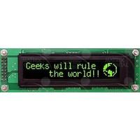
LCD Character Display Modules Black Background Yel/Grn Text
Manufacturer
Matrix Orbital
Series
PK202-25r
Datasheet
1.PK202-25.pdf
(50 pages)
Specifications of PK202-25
Character Count X Line
20 x 2
Module Size (w X H X T)
116 mm x 37 mm x 25.73 mm
Background Color
Black
Backlight Type
LED Yellow / Green
Lead Free Status / RoHS Status
Lead free / RoHS Compliant


To experiment, reverse the connector and see if it generates a more logical set of characters. Ultimately,
the program in your micro-controller will have to ‘map’ these characters to the ones marked on the keypad,
which will likely be different.
1.7 Manual Over-ride
rate which cannot be produced by the host system and all communication to the display is lost, then the user
should follow this simple procedure:
RS-232 port speed" command for acceptable baud rates.
2 Connections
2.1 Connector Pinout
Matrix Orbital
2. With the display connected to the PC, plug in the keypad. If the connector has fewer pins than the one
3. Press a key on the keypad. An upper case ASCII character (A-Y) should appear on the PC screen.
Manual over-ride should only be required in one instance. If for some reason the module is set at a baud
1. Load an appropriate test software that is located on the eCD (ex: displaytuner.exe)
2. Turn off the display.
3. Put a jumper on pins 5 and 6 of the keypad connector (C5 and R1).
4. Power up the display. The baud rate is now set to 19200 baud.
5. Remove the jumper and change the RS232 port settings to the desired baud rate. Refer to the "Set
6. Use “Display Tuner” or any other available test software to check functionality of the unit.
Try turning the display off/on, sending text, etc.
7. Turn off the display.
8. Power up the display.
Refer to the diagram below for this section.
on the display, center it as well as possible.
Different keys should generate different characters.
NOTES
• The keypad connector must be wired with columns on one side and rows on the other
• The connector is reversible. Reversing the connector will not damage the keypad or
side of the center of the connector. If the keypad isn’t wired this way an adapter must
be made or the connector must be rewired to meet this requirement.
the display, but it will change the ASCII character map.
PK202-25
4
Related parts for PK202-25
Image
Part Number
Description
Manufacturer
Datasheet
Request
R

Part Number:
Description:
LCD Character Display Modules Black Background Yel/Grn Text
Manufacturer:
Matrix Orbital

Part Number:
Description:
DISPLAY
Manufacturer:
Matrix Orbital
Datasheet:
Part Number:
Description:
LCD ACCY VFD FILTER 20X2 BLUE
Manufacturer:
Matrix Orbital
Datasheet:
Part Number:
Description:
LCD ACCY VFD FILTER 20X2 RED
Manufacturer:
Matrix Orbital
Datasheet:
Part Number:
Description:
LCD ACCY VFD FILTER 20X2 GREEN
Manufacturer:
Matrix Orbital
Datasheet:
Part Number:
Description:
LCD ACCY VFD FILTER 20X4 BLUE
Manufacturer:
Matrix Orbital
Datasheet:
Part Number:
Description:
LCD ACCY VFD FILTER 20X4 RED
Manufacturer:
Matrix Orbital
Datasheet:
Part Number:
Description:
LCD ACCY VFD FILTER 20X4 GREEN
Manufacturer:
Matrix Orbital
Datasheet:

Part Number:
Description:
DISPLAY
Manufacturer:
Matrix Orbital
Datasheet:

Part Number:
Description:
VFD DISPLAY 16X2 SER/I2C
Manufacturer:
Matrix Orbital
Datasheet:

Part Number:
Description:
VFD ALPHA/NUM DISPL 20X2 SER/I2C
Manufacturer:
Matrix Orbital
Datasheet:

Part Number:
Description:
VFD ALPHA/NUM DISPL 16X2 SER/I2C
Manufacturer:
Matrix Orbital
Datasheet:
Part Number:
Description:
VFD ALPHA/NUM DISPL 20X2 SER/I2C
Manufacturer:
Matrix Orbital
Datasheet: