B6TS-08NF Omron, B6TS-08NF Datasheet - Page 20
B6TS-08NF
Manufacturer Part Number
B6TS-08NF
Description
Capacitance Touch Sensors Sensing IC
Manufacturer
Omron
Series
-r
Type
Capacitiver
Specifications of B6TS-08NF
Supply Voltage
- 0.3 V to 6.5 V
Number Of Channels
8
Dimensions
9 mm L x 9 mm W x 1.7 mm H
Output Voltage
-0.3 V to Vsupply + 0.3 V
Power Dissipation
300 mW
Temperature Range
- 20 C to + 85 C
Termination Style
SMD/SMT
Sensitivity
-
Response Time
-
Interface
SPI
Channel Inputs
8 Key
Voltage - Supply
4.5 V ~ 5.5 V
Actuator Type
-
Package / Case
32-QFP
Lead Free Status / RoHS Status
Lead free / RoHS Compliant


Command code
Command code
Command code
6.2.14
6.2.15
6.2.16
0x3D
0x3E
0x3F
SLP: Sleep time (read/write enabled only in setup mode)
MODE: Operation mode (read/write enabled only in setup mode)
ROMSTR: EEPROM write (only write is enabled in setup mode)
DCF: Drift compensation type
TS: Teaching start
TER: Teaching error flag
DC: Drift compensation
CHG: CHG pin function
Defines the duty cycle between one measurement and the next measurement (operate time and sleep
time).
Sleep mode is activated for SLP value
When SLP is set to “0”, measurements are made consecutively without sleep time.
Only the lower-order 8 bits are valid. If the other bits are written to, they are ignored.
Select active mode.
Only the bits described are valid.
If the other bits are written to, they are ignored.
0: Teaching mode is entered when “0” is written in this bit.
1: During read out this bit is always "1"
Set/reset according to result of teaching.
Is set to “1” when teaching finishes normally.
If a teaching error occurs, this bit is set to "0".
This flag is not cleared automatically. To clear this flag, write "1" to this bit.
Enable/disable the drift compensation function.
1: Drift compensation is enabled. 0: Drift compensation is disabled.
Sets the target for drift compensation.
0: Only the reference value is corrected. The On-judgment variation quantity and hysteresis are not
1: All values are compensated (default).
The signal is specified from the CHG pin in normal measurement mode (serial communication mode).
With this pin set to “1”, when on/off changes in any channel (when any channel is touched (comes into
on state) or changes from touch to no-touch (goes to off state)), the signal is high.
When this pin is set to "0", the signal is high every time a measurement finishes.
When this command is issued by setting the data to 0x5354, all the parameter data are written to the
build in EEPROM
If the data is different than 0x5354, this command is ignored.
Until this command is issued, the written data is stored in RAM.
During write to the EEPROM, the CHG pin remains low.
TS
15
15
15
1
0
corrected.
TER
14
14
14
1
1
13
13
13
1
1
0
12
12
12
1
1
1
11
11
11
1
1
0
10
10
10
1
1
0
1
1
1
9
9
9
20
10mS (Typ)
8
1
8
1
8
1
D7
7
7
1
7
0
D6
6
6
1
6
1
D5
1
0
5
5
5
D4
4
4
1
4
1
DCF
D3
0
3
3
3
3713050-2A Ver.080123
D2
DC
2
2
2
1
CHG
D1
1
1
1
0
D0
0
0
0
1
0
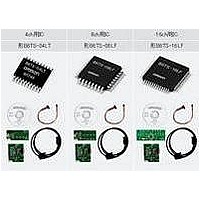
Related parts for B6TS-08NF
Image
Part Number
Description
Manufacturer
Datasheet
Request
R

Part Number:
Description:
SENSOR, CAP TOUCH, 4 CH, SMD, SOP20
Manufacturer:
Omron
Datasheet:

Part Number:
Description:
Capacitance Touch Sensors Sensing IC
Manufacturer:
Omron
Datasheet:

Part Number:
Description:
Capacitance Touch Sensors Touch Switch
Manufacturer:
Omron
Datasheet:

Part Number:
Description:
G6S-2GLow Signal Relay
Manufacturer:
Omron Corporation
Datasheet:
Part Number:
Description:
Compact, Low-cost, SSR Switching 5 to 20 A
Manufacturer:
Omron Corporation
Datasheet:
Part Number:
Description:
Manufacturer:
Omron Corporation
Datasheet:
Part Number:
Description:
Manufacturer:
Omron Corporation
Datasheet:
Part Number:
Description:
Manufacturer:
Omron Corporation
Datasheet:
Part Number:
Description:
Manufacturer:
Omron Corporation
Datasheet:
Part Number:
Description:
Manufacturer:
Omron Corporation
Datasheet: