RC0805FR-1310KL Yageo, RC0805FR-1310KL Datasheet - Page 3
RC0805FR-1310KL
Manufacturer Part Number
RC0805FR-1310KL
Description
RESISTOR, THICK FILM, 10KOHM, 125mW, 1%
Manufacturer
Yageo
Series
RC0805r
Datasheet
1.RL2512FK-070R2L.pdf
(8 pages)
Specifications of RC0805FR-1310KL
Resistance
10kohm
Resistance Tolerance
± 1%
Power Rating
125mW
Voltage Rating
150V
Resistor Element Material
Thick Film
Temperature Coefficient
± 100ppm/°C
Tolerance
1 %
Termination Style
SMD/SMT
Package / Case
0805 (2013 metric)
Operating Temperature Range
- 55 C to + 155 C
Dimensions
1.25 mm W x 2 mm L x 0.5 mm H
Product
Thick Film Resistors SMD
Lead Free Status / RoHS Status
Lead free / RoHS Compliant
Lead Free Status / RoHS Status
Lead free / RoHS Compliant


CONSTRUCTION
The resistor is constructed on top of a high-grade
ceramic body. Internal metal electrodes are added
on each end to make the contacts to the thick film
resistive element. The composition of the resistive
element is a noble metal embedded into a glass and
covered by a second glass to prevent environmental
influences. The resistor is laser trimmed to the rated
resistance value. The resistor is covered with a
protective epoxy coat, finally the two external
terminations (matte tin on Ni-barrier) are added.
See fig. 3.
DIMENSIONS
MARKING
RC0603/0805/1206/2512
For further marking information, please see special data sheet “Chip resistors marking”.
TYPE
RC0603
RC0805
RC1206
RC2512
Dec 14, 2010 V.0
Table 1 For outlines see fig. 3
Fig. 1
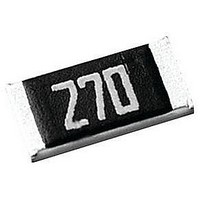
Fig. 2 Value=10 KΩ
1.60 ±0.10 0.80 ±0.10 0.45 ±0.10 0.25 ±0.15 0.25 ±0.15
2.00 ±0.10 1.25 ±0.10 0.50 ±0.10 0.35 ±0.20 0.35 ±0.20
3.10 ±0.10 1.60 ±0.10 0.55 ±0.10 0.45 ±0.20 0.40 ±0.20
6.35 ±0.10 3.10 ±0.15 0.55 ±0.10 0.60 ±0.20 0.50 ±0.20
Value=10 KΩ
L (mm) W (mm)
00
03
Chip Resistor Surface Mount
YNSC001
YNSC004
H (mm)
E-24 series: 3 digits for 5%
First two digits for significant figure and 3rd digit for number of zeros
Both E-24 and E-96 series: 4 digits for 1%
First three digits for significant figure and 4th digit for number of zeros
I
1
(mm)
I
2
RC-High power
(mm)
O
O
U
U
For dimension see Table 1
H
W
Fig. 3 Chip resistor outlines
T
T
SERIES
L
L
I
I
N
N
I 2
I
1
E
E
S
S
0603 to 2512
L
Product specification
marking layer
overcoat
Primary glass layer
resistive layer
(Jumper chip is a conductor)
inner electrode
termination (Ni/matte tin)
ceramic substrate
overcoat
www.yageo.com
3
8
Related parts for RC0805FR-1310KL
Image
Part Number
Description
Manufacturer
Datasheet
Request
R

Part Number:
Description:
RES SMD 0805 1K20 1% 0.125W TC100 10 Reel
Manufacturer:
Yageo
Part Number:
Description:
RES SMD 0805 1K80 1% 0.125W TC100 10 Reel
Manufacturer:
Yageo
Part Number:
Description:
RES SMD 0805 33K0 1% 0.125W TC100 10 Reel
Manufacturer:
Yageo
Part Number:
Description:
RES SMD 0805 6K80 1% 0.125W TC100 10 Reel
Manufacturer:
Yageo
Part Number:
Description:
RES SMD 0805 680K 1% 0.125W TC100 10 Reel
Manufacturer:
Yageo
Part Number:
Description:
RES SMD 0805 1K00 1% 0.125W TC100 13 Reel
Manufacturer:
Yageo
Part Number:
Description:
RES SMD 0805 162R 1% 0.125W TC100 13 Reel
Manufacturer:
Yageo
Part Number:
Description:
RES SMD 0805 180K 1% 0.125W TC100 13 Reel
Manufacturer:
Yageo
Part Number:
Description:
RES SMD 0805 1M80 1% 0.125W TC100 13 Reel
Manufacturer:
Yageo
Part Number:
Description:
RES SMD 0805 2K20 1% 0.125W TC100 13 Reel
Manufacturer:
Yageo
Part Number:
Description:
RES SMD 0805 22K0 1% 0.125W TC100 13 Reel
Manufacturer:
Yageo
Part Number:
Description:
RES SMD 0805 3K30 1% 0.125W TC100 13 Reel
Manufacturer:
Yageo
Part Number:
Description:
RES SMD 0805 33K0 1% 0.125W TC100 13 Reel
Manufacturer:
Yageo
Part Number:
Description:
RES SMD 0805 4K70 1% 0.125W TC100 13 Reel
Manufacturer:
Yageo
Part Number:
Description:
RES SMD 0805 5K60 1% 0.125W TC100 13 Reel
Manufacturer:
Yageo