P11S1V0FLSY00503KA Vishay, P11S1V0FLSY00503KA Datasheet - Page 8
P11S1V0FLSY00503KA
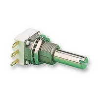
Manufacturer Part Number
P11S1V0FLSY00503KA
Description
POTENTIOMETER, 50K POTENTIOMETER, 50K
Manufacturer
Vishay
Series
P11r
Datasheet
1.P11S1A0BGSY00101KA.pdf
(15 pages)
Specifications of P11S1V0FLSY00503KA
Resistors Element Type
VARIABLE ROTARY CERMET
Resistance, Track
50KR
Power Rating
1W
Case Style
PANEL MOUNT
Temp, Op. Max
125(DEGREE C)
Temp, Op. Min
-55(DEGREE C)
Temp. Coeff,
ROHS COMPLIANT
Resistance
50 KOhms
Tolerance
10 %
Termination Style
SMD/SMT
Taper
Linear
Number Of Turns
1
Element Type
Cermet
Shaft Type
Slotted
Shaft Length
25 mm
Shaft Diameter
6 mm
Operating Temperature Range
- 55 C to + 125 C
Product
Modular Panel Potentiometer
Lead Free Status / Rohs Status
Lead free / RoHS Compliant


Document Number: 51031
Revision: 21-Feb-11
W
Y Soldering lugs
X PCB pins
A PCB pins with front and back support plates
MODEL
Z PCB pins with front support plate
E
E
E
J
ORDERING INFORMATION (Part Number)
DIMENSIONS in millimeters (inches) ± 0.5 mm (± 0.02")
THE POSITION OF EACH MODULE IS FREE
PCB pins - vertical mounting with 2 extra
pins - 1 module only
P
FRONT AND REAR SUPPORT PLATES
Leads Z0. with Rotary Switch
2
1
3
STYLE
Leads Z1. Z2. A..
BUSHINGS
1
Leads X.. Y..
A/A2
FIRST DIGIT
Leads Z00
(0.150)
3.81
E
MODULES
F
NUMBER
J
1
F
OF
(0.150)
3.81
S
Cermet (P11S) or Conductive Plastic Elements (P11A)
See also Application Note:
BUSHING
2
(0.146)
Rear support
plate
(0.250)
HORIZONTAL MOUNTING
6.35
(0.270)
3.71
A1
6.85
SOLDER LUGS Y
12.5 mm Modular Panel Potentiometer
3.15
1.45
Q
2.8
6.7
G
LOCATING
DIMENSIONS mm (± 0.5)
0
1
2
Leads Z0.: 5.08 (0.200")
(0.185)
For technical questions, contact:
(0.492)
PEG
0
Y = 4.65 (0.183")
A, X, Z, W = 5.08 (0.200") pin spacing
pins section 0.9 x 0.3 (0.035" x 0.012")
2.54 (0.100") pin spacing
pin section 0.6 x 0.3 (0.024" x 0.012")
5.08 (0.200") pin spacing
pins section 0.6 x 0.3 (0.024" x 0.012")
12.5
4.7
1.85
0.15
1.6
T
5
(0.200)
5.08
(0.492)
www.vishay.com/doc?51001
12.5
E
1 2 3
SHAFT
SECOND DIGIT
Z
1.85
0.15
FRONT SUPPORT PLATE
(0.512)
(0.185)
1.6
Q
5
4.7
A
13
(0.200)
5.08
(0.100)
2.54
(0.197)
S
3.85
2.15
3.6
SHAFT
STYLE
V
7
123
5
Z
1
(0.150)
Y
3.81
(0.035)
(0.07)
(0.200)
0.9
0.071
0.063
0.200
0.006
sfer@vishay.com
1.8
5.08
A
(0.09)
A00 W00 X00 Y00 Z00
A10 W10 X03 Y03 Z03
A13 W20 X04 Y04 Z04
A14
A20
A23
A24
and
2.4
(0.035)
0
1 2 3
0.9
Z
www.vishay.com/doc?52029
2
0.071
0.063
0.200
0.006
Available leads
(0.150)
3.81
B
DIMENSIONS INCHES (± 0.02)
0
Leads A.. Z1. Z2.: 3.81 (0.150")
0 5.08 (0.200") space between modules
3 7.62 (0.300") space between modules
4 10.16 (0.400") space between modules
LEADS
X10
X13
X14
X20
X23
X24
0.071
0.063
0.200
0.006
1
C
1
VERTICAL MOUNTING
X
W-W2
X -
2 3
A
1 2 3
PCB PIN OUT
0
2
Z10
Z13
Z14
Z20
Z23
Z24
(0.200)
THIRD DIGIT
5.08
(0.200)
0.071
0.063
0.200
0.006
B
5.08
Vishay Sfernice
D
(0.500)
12.7
C
P11S, P11A
3
RESISTANCE CODE/
TAPER OR SPECIAL
K
123
X1
TOLERANCE/
12 3
0.071
0.063
0.200
0.006
W1
(0.500)
M
E
(0.100)
12.7
www.vishay.com
(0.157)
(0.100)
2.54
2.54
(0.500)
4
12.7
A
0.0846
0.150
0.140
0.278
F
8
Related parts for P11S1V0FLSY00503KA
Image
Part Number
Description
Manufacturer
Datasheet
Request
R

Part Number:
Description:
357-036-542-201 CARDEDGE 36POS DL .156 BLK LOPRO
Manufacturer:
Vishay
Datasheet:
Part Number:
Description:
357-036-542-201 CARDEDGE 36POS DL .156 BLK LOPRO
Manufacturer:
Vishay
Datasheet:
Part Number:
Description:
357-036-542-201 CARDEDGE 36POS DL .156 BLK LOPRO
Manufacturer:
Vishay
Datasheet:
Part Number:
Description:
357-036-542-201 CARDEDGE 36POS DL .156 BLK LOPRO
Manufacturer:
Vishay
Datasheet:
Part Number:
Description:
357-036-542-201 CARDEDGE 36POS DL .156 BLK LOPRO
Manufacturer:
Vishay
Datasheet:
Part Number:
Description:
357-036-542-201 CARDEDGE 36POS DL .156 BLK LOPRO
Manufacturer:
Vishay
Datasheet:
Part Number:
Description:
357-036-542-201 CARDEDGE 36POS DL .156 BLK LOPRO
Manufacturer:
Vishay
Datasheet:
Part Number:
Description:
357-036-542-201 CARDEDGE 36POS DL .156 BLK LOPRO
Manufacturer:
Vishay
Datasheet:
Part Number:
Description:
357-036-542-201 CARDEDGE 36POS DL .156 BLK LOPRO
Manufacturer:
Vishay
Datasheet:
Part Number:
Description:
357-036-542-201 CARDEDGE 36POS DL .156 BLK LOPRO
Manufacturer:
Vishay
Datasheet:
Part Number:
Description:
357-036-542-201 CARDEDGE 36POS DL .156 BLK LOPRO
Manufacturer:
Vishay
Datasheet:
Part Number:
Description:
357-036-542-201 CARDEDGE 36POS DL .156 BLK LOPRO
Manufacturer:
Vishay
Datasheet:
Part Number:
Description:
357-036-542-201 CARDEDGE 36POS DL .156 BLK LOPRO
Manufacturer:
Vishay
Datasheet:
Part Number:
Description:
357-036-542-201 CARDEDGE 36POS DL .156 BLK LOPRO
Manufacturer:
Vishay
Datasheet:
Part Number:
Description:
357-036-542-201 CARDEDGE 36POS DL .156 BLK LOPRO
Manufacturer:
Vishay
Datasheet: