P11S1V0FLSY00503KA Vishay, P11S1V0FLSY00503KA Datasheet - Page 13
P11S1V0FLSY00503KA
Manufacturer Part Number
P11S1V0FLSY00503KA
Description
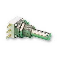
POTENTIOMETER, 50K POTENTIOMETER, 50K
Manufacturer
Vishay
Series
P11r
Datasheet
1.P11S1A0BGSY00101KA.pdf
(15 pages)
Specifications of P11S1V0FLSY00503KA
Resistors Element Type
VARIABLE ROTARY CERMET
Resistance, Track
50KR
Power Rating
1W
Case Style
PANEL MOUNT
Temp, Op. Max
125(DEGREE C)
Temp, Op. Min
-55(DEGREE C)
Temp. Coeff,
ROHS COMPLIANT
Resistance
50 KOhms
Tolerance
10 %
Termination Style
SMD/SMT
Taper
Linear
Number Of Turns
1
Element Type
Cermet
Shaft Type
Slotted
Shaft Length
25 mm
Shaft Diameter
6 mm
Operating Temperature Range
- 55 C to + 125 C
Product
Modular Panel Potentiometer
Lead Free Status / Rohs Status
Lead free / RoHS Compliant


P11S, P11A
Vishay Sfernice
www.vishay.com
13
P11 OPTION: CENTER CURRENT TAP “J”
The extra terminal is a solder lug connected at 50 % of electrical
travel and siluated in the potentiometer module opposite the
terminals.
Center tap presents a short circuit of 11° of travel.
ORDERING INFORMATION (First order only)
J
P11 OPTION: SPECIAL LINEARITY - CONFORMITY
ORDERING INFORMATION (First order only)
J123
J145
P11 OPTION: SPECIAL INTERLINEARITY - INTERCONFORMITY
ORDERING INFORMATION (First order only)
J44
J123
J44
V
Center tap
Independent linearity ± 3 % (linear law)
Independent linearity ± 2 % (linear law)
Interlinearity ± 2 % (linear taper)
J
E
C
100 %
V
E
50 %
0 %
V
See also Application Note:
Effective electrical travel
Effective electrical travel
Limits of test
V1
linearity test
V2
V1
Cermet (P11S) or Conductive Plastic Elements (P11A)
Limits of
V2
11°
For technical questions, contact:
12.5 mm Modular Panel Potentiometer
Degrees
www.vishay.com/doc?51001
Degrees
sfer@vishay.com
• Sealing IP60
The independent linearity (conformity for the non linear laws) is
the maximum gap V between the actual variation curve and the
theorical variation curve the nearest to it. The linearity and the
conformity are expressed in percentage of the total applied
voltage E
They are measured over 90 % of actual electrical travel
(centered).
On request linearity can be guaranteed in linear taper.
For other request, contact us.
It is the maximum deviation between the actual voltage outputs
of 2 or more pot modules in the same assembly. It is expressed
as a percentage of the total applied voltage, or in dB attenuation.
Interlinearity is measured between 2 pot modules, over 10 to
90 % of the attenuation.
The interlinearity or interconformity is expressed as a
percentage of the total applied voltage:
Or in decibels by comparison between outputs V1 and V2
For other request, contact us.
and
www.vishay.com/doc?52029
linearity conformity
I dB
I %
=
20 log
=
------ -
C
E
=
V
----- -
V
± V
---------------------- -
Document Number: 51031
1
2
E
max.
Revision: 21-Feb-11
Related parts for P11S1V0FLSY00503KA
Image
Part Number
Description
Manufacturer
Datasheet
Request
R

Part Number:
Description:
357-036-542-201 CARDEDGE 36POS DL .156 BLK LOPRO
Manufacturer:
Vishay
Datasheet:
Part Number:
Description:
357-036-542-201 CARDEDGE 36POS DL .156 BLK LOPRO
Manufacturer:
Vishay
Datasheet:
Part Number:
Description:
357-036-542-201 CARDEDGE 36POS DL .156 BLK LOPRO
Manufacturer:
Vishay
Datasheet:
Part Number:
Description:
357-036-542-201 CARDEDGE 36POS DL .156 BLK LOPRO
Manufacturer:
Vishay
Datasheet:
Part Number:
Description:
357-036-542-201 CARDEDGE 36POS DL .156 BLK LOPRO
Manufacturer:
Vishay
Datasheet:
Part Number:
Description:
357-036-542-201 CARDEDGE 36POS DL .156 BLK LOPRO
Manufacturer:
Vishay
Datasheet:
Part Number:
Description:
357-036-542-201 CARDEDGE 36POS DL .156 BLK LOPRO
Manufacturer:
Vishay
Datasheet:
Part Number:
Description:
357-036-542-201 CARDEDGE 36POS DL .156 BLK LOPRO
Manufacturer:
Vishay
Datasheet:
Part Number:
Description:
357-036-542-201 CARDEDGE 36POS DL .156 BLK LOPRO
Manufacturer:
Vishay
Datasheet:
Part Number:
Description:
357-036-542-201 CARDEDGE 36POS DL .156 BLK LOPRO
Manufacturer:
Vishay
Datasheet:
Part Number:
Description:
357-036-542-201 CARDEDGE 36POS DL .156 BLK LOPRO
Manufacturer:
Vishay
Datasheet:
Part Number:
Description:
357-036-542-201 CARDEDGE 36POS DL .156 BLK LOPRO
Manufacturer:
Vishay
Datasheet:
Part Number:
Description:
357-036-542-201 CARDEDGE 36POS DL .156 BLK LOPRO
Manufacturer:
Vishay
Datasheet:
Part Number:
Description:
357-036-542-201 CARDEDGE 36POS DL .156 BLK LOPRO
Manufacturer:
Vishay
Datasheet:
Part Number:
Description:
357-036-542-201 CARDEDGE 36POS DL .156 BLK LOPRO
Manufacturer:
Vishay
Datasheet: