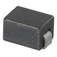
2743037447 Fair-Rite, 2743037447 Datasheet - Page 184

2743037447
Manufacturer Part Number
2743037447
Description
CHIP BEAD,Ferrite
Manufacturer
Fair-Rite
Datasheet
1.2743037447.pdf
(193 pages)
Specifications of 2743037447
Lead Free Status / RoHS Status
Lead free / RoHS Compliant
- Current page: 184 of 193
- Download datasheet (7Mb)
Fair-Rite Products Corp.
Phone: (888) FAIR RITE / (845) 895-2055
Technical Information
184
Figure 3
Wide Angle Absorption
One of the most overlooked aspects of using any absorber is the
rolloff of absorption with increasing angle of incidence. Most
published absorber data contains only normal incidence return
loss (dB) which is typically where the maximum absorption is
obtained. Normal incidence is defined as plane wave radation
arriving perpendicular (0°) to the plane of the absorbing surface.
The curves in Figure 4 were generated using equations de-
scribed in IEEE document “Recommended Practice for RF
Absorber Evaluation in the range 30 MHz to 5 GHz”. Since the
reflections occuring in anechoic chambers seldom illuminate
absorber materials at 0°, it is important to consider the reflection
angles generated by each chamber geometry and size for best
results. For most chambers, the range of angles is in the 40-60°
range, however it is usually desirable to operate at < 50°.
-10
-15
-20
-25
-30
-35
-40
-45
-50
-5
0
10
Figure 2
(888) 324-7748
Typical Return Loss with Dielectric Spacer
100
Ferrite
Dielectric
5.4mm
6.3mm
Spacer
Frequency (MHz)
6.0mm
5.7mm
Spacer Thickness = 13mm
1000
Metal
Wall
• FAX: (888) FERRITE / (845) 895-2629 • www.fair-rite.com • E-Mail: ferrites@fair-rite.com
(888) 337-7483
10000
Return loss vs angle of incidence for TM polarization is shown
in Figure 4. Return loss curves for TE polarization (not shown)
are similar.
Figure 4
Precision Dimensions
Studies have shown that maximum low-frequency performance
is obtained when tile to tile gaps are minimized.
precisely machines each of the six surfaces to ± 0.13mm (.005”)
to ensure a tight tile to tile fit for easier installation with less cutting
required. Figure 5 illustrates the effect of gaps on tile perfor-
mance when installed with: no gap (0mm), .25mm and 1.0mm.
It is critical to maintain contact between tiles for best results. The
final results of the completed test chamber will also be degraded
by other factors such as lights, gaps around door openings, and
exposed metallic conduit.
Figure 5
P.O. Box J,One Commercial Row, Wallkill, NY 12589-0288
-10
-15
-20
-25
-30
-35
-40
Note: (914) Area Code has changed to (845).
-10
-15
-20
-25
-30
-35
-40
-5
-5
0
0
10
10
Wide-Angle Return Loss – TM Polarization
1
Reflectivity vs. Tile – Tile Gap Size
75˚
60˚
45˚
30˚
0˚
100
1.0mm
.25mm
0mm
Frequency (MHz)
Frequency (MHz)
1000
14th Edition
Fair-Rite
10000
10
2
Related parts for 2743037447
Image
Part Number
Description
Manufacturer
Datasheet
Request
R

Part Number:
Description:
Standoff, 1/4 Inch Round, Female/Female, 8-32 Thread, 2 Inch Length, Aluminum, Clear Iridite Finish
Manufacturer:
SPC TECHNOLOGY

Part Number:
Description:
EMI/RFI Suppressors & Ferrites LF Z=95OHM @ 100MHz
Manufacturer:
Fair-Rite

Part Number:
Description:
EMI/RFI Suppressors & Ferrites Z=94ohms @ 10MHz
Manufacturer:
Fair-Rite
Datasheet:

Part Number:
Description:
EMI/RFI Suppressors & Ferrites LF Z=47OHM @ 100MHz
Manufacturer:
Fair-Rite
Datasheet:

Part Number:
Description:
EMI/RFI Suppressors & Ferrites Z=300 @ 100MHz
Manufacturer:
Fair-Rite
Datasheet:

Part Number:
Description:
EMI/RFI Suppressors & Ferrites Z=365 OHM @ 100 MHz
Manufacturer:
Fair-Rite
Datasheet:

Part Number:
Description:
EMI/RFI Suppressors & Ferrites LF Z=133OHM @ 100MHz T/R
Manufacturer:
Fair-Rite
Datasheet:

Part Number:
Description:
EMI/RFI Suppressors & Ferrites Z=132 OHM @ 100MHz
Manufacturer:
Fair-Rite
Datasheet:

Part Number:
Description:
EMI/RFI Suppressors & Ferrites Z=33 OHM @ 100MHz
Manufacturer:
Fair-Rite
Datasheet:

Part Number:
Description:
EMI/RFI Suppressors & Ferrites LF Z=78OHM @ 25MHz
Manufacturer:
Fair-Rite
Datasheet:

Part Number:
Description:
FERRITE CORE, CYLINDRICAL
Manufacturer:
Fair-Rite
Datasheet:

Part Number:
Description:
FERRITE BEAD, SMD, 350mOHM, 400mA
Manufacturer:
Fair-Rite
Datasheet:

Part Number:
Description:
FERRITE CORE, CYLINDRICAL
Manufacturer:
Fair-Rite
Datasheet:

Part Number:
Description:
FERRITE BEAD, SMD, 1.4mOHM, 5A
Manufacturer:
Fair-Rite
Datasheet:

Part Number:
Description:
SPLIT FERRITE CORE, 100MHZ, 290OHM
Manufacturer:
Fair-Rite
Datasheet:


