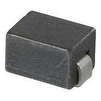
2743037447 Fair-Rite, 2743037447 Datasheet - Page 165

2743037447
Manufacturer Part Number
2743037447
Description
CHIP BEAD,Ferrite
Manufacturer
Fair-Rite
Datasheet
1.2743037447.pdf
(193 pages)
Specifications of 2743037447
Lead Free Status / RoHS Status
Lead free / RoHS Compliant
- Current page: 165 of 193
- Download datasheet (7Mb)
14th Edition
P.O. Box J,One Commercial Row, Wallkill, NY 12589-0288
Phone: (888) FAIR RITE / (845) 895-2055
Introduction
If ferrite cores are used in the design of transformers, chokes or
filters, which are required to carry direct current, it is necessary
to predict the degree of inductance degradation caused by the
static field. When dc flows through the winding of a ferromagnetic
device, it tends to pre-magnetize the core and reduce its induc-
tance. The permeability of a ferrite material measured with
superimposed dc might increase slightly for very low values of
dc ampere-turns, but then it progressively decreases as the dc
field is increased and the core approaches saturation. This
permeability is referred to as the incremental permeability m
an air gap is introduced into the magnetic path of a core, the
reluctance is increased hence the inductance is decreased.
However, the core’s capacity for dc ampere-turns without a
degradation in inductance is significantly improved, albeit at the
expense of a lower effective permeability.
DC Bias in Gapped Cores
The use of graphs such as the Hanna* curves has simplified the
tedious trial and error methods often employed when designing
inductors with superimposed dc. A Hanna curve is created by
measuring the inductance vs. dc bias of various core sizes and
gap lengths of the same material grade. The measured data is
used to create curves such as those plotted in Figure 1 (this curve
is specific for a set of 9478015002 E cores). A line is drawn
connecting the individual curves through the point of tangency.
The graphs are then normalized by dividing the vertical scale of
Figure 1 by the effective core volume V
and the gap lengths by the effective path length
The individual curves, once normalized, overlay creating the
Hanna curve. Figure 2 is such a curve for Fair-Rite 78 material
and can be used for all core sets in that material.
The Effect of Direct Current on the
Inductance of a Ferrite Core
*Footnote:
The paper provided a method of calculating the air gap that will yield the maximum inductance for a given number of turns, with a specified amount of dc,
for a particular material.
(888) 324-7748
C.R. Hanna presented a paper “Design of Reactances and Transformers which Carry Direct Current” at the 1927 Winter Convention of AIEE.
e
and the horizontal scale
• FAX: (888) FERRITE / (845) 895-2629 • www.fair-rite.com • E-Mail: ferrites@fair-rite.com
l
e
of the core set.
Technical Information
(888) 337-7483
D
. If
Fair-Rite Products Corp.
Figure 1
Design Example
For a typical output choke application, the designer knows a
number of design criteria such as the required inductance, the
direct current, alternating ripple current and allowable dc resis-
tance. He will also have requirements for core size, ambient
temperature an often a preference for a particular core geometry.
A
Note: (914) Area Code has changed to (845).
L
I
2
10
10
10
10
10
-5
-6
-7
-8
-9
Product inductance factor and current squared vs.
DC current for a pair of 9478015002 E cores.
0.01
Bias Current (A)
0.1
air gap
.000
.001
1
.003
.010
.020
.040
10
165
Related parts for 2743037447
Image
Part Number
Description
Manufacturer
Datasheet
Request
R

Part Number:
Description:
Standoff, 1/4 Inch Round, Female/Female, 8-32 Thread, 2 Inch Length, Aluminum, Clear Iridite Finish
Manufacturer:
SPC TECHNOLOGY

Part Number:
Description:
EMI/RFI Suppressors & Ferrites LF Z=95OHM @ 100MHz
Manufacturer:
Fair-Rite

Part Number:
Description:
EMI/RFI Suppressors & Ferrites Z=94ohms @ 10MHz
Manufacturer:
Fair-Rite
Datasheet:

Part Number:
Description:
EMI/RFI Suppressors & Ferrites LF Z=47OHM @ 100MHz
Manufacturer:
Fair-Rite
Datasheet:

Part Number:
Description:
EMI/RFI Suppressors & Ferrites Z=300 @ 100MHz
Manufacturer:
Fair-Rite
Datasheet:

Part Number:
Description:
EMI/RFI Suppressors & Ferrites Z=365 OHM @ 100 MHz
Manufacturer:
Fair-Rite
Datasheet:

Part Number:
Description:
EMI/RFI Suppressors & Ferrites LF Z=133OHM @ 100MHz T/R
Manufacturer:
Fair-Rite
Datasheet:

Part Number:
Description:
EMI/RFI Suppressors & Ferrites Z=132 OHM @ 100MHz
Manufacturer:
Fair-Rite
Datasheet:

Part Number:
Description:
EMI/RFI Suppressors & Ferrites Z=33 OHM @ 100MHz
Manufacturer:
Fair-Rite
Datasheet:

Part Number:
Description:
EMI/RFI Suppressors & Ferrites LF Z=78OHM @ 25MHz
Manufacturer:
Fair-Rite
Datasheet:

Part Number:
Description:
FERRITE CORE, CYLINDRICAL
Manufacturer:
Fair-Rite
Datasheet:

Part Number:
Description:
FERRITE BEAD, SMD, 350mOHM, 400mA
Manufacturer:
Fair-Rite
Datasheet:

Part Number:
Description:
FERRITE CORE, CYLINDRICAL
Manufacturer:
Fair-Rite
Datasheet:

Part Number:
Description:
FERRITE BEAD, SMD, 1.4mOHM, 5A
Manufacturer:
Fair-Rite
Datasheet:

Part Number:
Description:
SPLIT FERRITE CORE, 100MHZ, 290OHM
Manufacturer:
Fair-Rite
Datasheet:


