23.0410-21 MC (MULTI CONTACT), 23.0410-21 Datasheet - Page 2
23.0410-21
Manufacturer Part Number
23.0410-21
Description
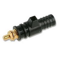
CONNECTOR, PANEL MOUNT, BLACK
Manufacturer
MC (MULTI CONTACT)
Series
SPK4r
Datasheet
1.23.0410-21.pdf
(2 pages)
Specifications of 23.0410-21
Contact Termination
Screw
Voltage Rating
600VAC
Contact Plating
Gold
Connector Colour
Black
Connector Mounting
Panel
Svhc
No SVHC (15-Dec-2010)
Colour
Contact
Current Rating
32A


2/2
a
b
(SAB4-G)
(SAB4-G/N)
(SAB4-GT/N)
®
8.2
a
ill.4
a
b
ill.10
ill.5
ill.6
ill.7
ill.8
ill.9
G
(SPK4)
10
a
MA153
www.multi-contact.com
Montage
(ill.4)
Fronttafel bohren.
Bohrung für SAB4-G,
SAB4-G/N-X
SAB4-GT/N: 8,2 mm.
Bohrung für SPK4:
10 mm.
Plattenstärke:
für SAB4-G,
SAB4-GT/N: max. 3 mm.
Für SPK4: max. 4 mm
Als Auflage der Fronttafel
wird vorzugsweise ein
Kunststoffrohr verwen-
det. Der Durchmesser
des Auflagerohres richtet
sich nach den gewählten
Lochabständen.
(ill.5)
Sicherheitsbuchse in
Fronttafel stecken.
(ill.6)
Von der Rückseite her Ge-
genstück (G), Unterleg-
scheiben und Muttern in
der gezeigten Reihenfolge
aufstecken bzw. auf-
schrauben.
(ill.7)
Mutter von Hand leicht an-
ziehen.
(ill.8)
(gilt nur für SAB4-G,
SAB4-G/N-X
SAB4-GT/N):
Mit dem Drehmoment-
schlüssel (7mm) die Be-
festigungsmutter (a) an-
ziehen und gleichzeitig
den Spezialschlüssel SS2
zum Kontern in die Buchse
stecken, bis er in den dafür
vorgesehenen Vertiefung-
en einrastet.
Anzugsdrehmoment:
max.
(gilt nur für SPK4):
Mit dem Gabelschlüssel
(8mm) die Befestigungs-
mutter (a) anziehen und da-
bei die Sicherheitsbuchse
mit der Hand festhalten.
Anzugsdrehmoment:
max. 70Ncm.
(ill.9)
Zum Anschliessen der Lei-
tung die Spannscheiben
und die Mutter in der ge-
zeigten Reihenfolge auf-
stecken bzw. aufschrau-
ben.
(ill.10)
Wichtig:
Beim Anziehen der Mutter
(b) muss mit der Mutter (a)
gekontert werden!
70 Ncm.
10/04
SAB4-G/N-X,
und
und
Index c
Änderungen vorbehalten/Subject to alterations/Modifications sous réserve.
Copyright by Multi-Contact AG, Switzerland MC-
Assembly
(ill.4)
Drill hole in the front pa-
nel.
For SAB4-G, SAB4-G/N-X
and SAB4-GT/N: 8.2 mm.
For SPK4: 10 mm.
Panel thickness:
for SAB4-G, SAB4-G/N-X,
SAB4-GT/N: max. 3 mm.
For SPK4: max. 4 mm
As an assembly support
for the front panel, a plas-
tic tube can be used. The
tube diameter depends
upon the desired spa-
cings between the so-
ckets.
(ill.5)
Place safety socket into
the front panel.
(ill.6)
From the back, in the
order shown, assemble
the insulator (G), the
washers and nuts.
(ill.7)
Lightly tighten the nut by
hand.
(ill.8)
(applies only to SAB4-G,
SAB4-G/N-X
SAB4-GT/N):
Using the torque spanner
(7mm), tighten the fixing
nut (a) and at the same
time, in order to counter-
tighten, insert the special
wrench SS2 into the so-
cket until it engages in the
recess provided.
Tightening torque:
max. 70 Ncm.
(applies only to SPK 4):
Using an open-ended
spanner (8mm), screw
down the fixing nut (a)
while holding the safety
socket firm in the hand.
Tightening torque:
max. 70 Ncm.
(ill.9)
To connect the cable, fit
the spring washers and
screw on the nut in the
order shown.
(ill.10)
Important:
When tightening nut (b),
nut (a) must be used to
counter.
and
Multi-Contact
Montage
(ill.4)
Percer le panneau. Perçage
pour SAB4-G, SAB4-G/N-X et
SAB4-GT/N: 8, 2 mm.
Perçage pour SPK4:
10 mm.
Epaisseurs des plaques:
pour SAB4-G, SAB4-G/N-X,
SAB4-GT/N: max. 3 mm.
Pour SPK4: max. 4 mm
Utiliser de préférence un tu-
be en matière plastique
comme support de monta-
ge. Le diamètre du tube dé-
pend de la distance entre
deux douilles voisines.
(ill.5)
Introduire la douille de sécu-
rité dans le panneau.
(ill.6)
Monter par
cessoires (écrous cylindri-
ques, rondelles et
tre-pièce G) en respectant
l'ordre d'assemblage.
(ill.7)
Serrer légèrement l'écrou
à la main.
(ill.8)
(uniquement valable
pour SAB4-G,
SAB4-G/N-X et
SAB4-GT/N):
Avec la clé dynamométri-
que (7mm), serrer l'écrou
(a) tout en contrant avec la
clé spéciale SS2. Veiller à
bien introduire cette clé
dans les logements cor-
respondant au fond de la
douille.
Couple de serrage:
max 70 Ncm.
(uniquement valable
Avec la clé dynamométri-
que (8mm), serrer l'écrou
(a) tout en contrant avec la
main.
Couple de serrage: max.
70Ncm.
(ill.9)
Pour raccorder le câble
monter les rondelles et
l'écrou en respectant l'or-
dre d'assemblage.
(ill.10)
Important:
Lors du serrage de l'écrou
(b), contrer impérative-
ment avec l'écrou (a).
pour SPK4):
T&M
line
l'arrière les ac-
500-10/04
la con-
Related parts for 23.0410-21
Image
Part Number
Description
Manufacturer
Datasheet
Request
R

Part Number:
Description:
CONNECTOR, PANEL MOUNT, RED
Manufacturer:
MC (MULTI CONTACT)
Datasheet:

Part Number:
Description:
FUSE, 0.5A, MC CAT IV
Manufacturer:
MC (MULTI CONTACT)
Datasheet:
Part Number:
Description:
FUSE, 1.6A, MC CAT IV
Manufacturer:
MC (MULTI CONTACT)
Datasheet:

Part Number:
Description:
CAP, PROTECTIVE, BLACK
Manufacturer:
MC (MULTI CONTACT)
Datasheet: