B51-328-3188220 ITT SEALECTRO, B51-328-3188220 Datasheet - Page 7
B51-328-3188220
Manufacturer Part Number
B51-328-3188220
Description
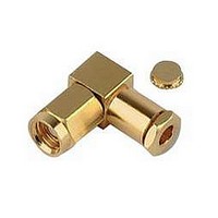
RF/COAXIAL, SMB PLUG, R/A, 50OHM, CRIMP
Manufacturer
ITT SEALECTRO
Datasheet
1.B50-051-0000220.pdf
(64 pages)
Specifications of B51-328-3188220
Body Style
Right Angle Plug
Coaxial Termination
Crimp
Rg Cable Type
RG-174, 316
Contact Material
Beryllium Copper
Contact Plating
Gold
Connector Type
SMB Coaxial
Impedance
50ohm
Lead Free Status / RoHS Status
Lead free / RoHS Compliant


frequency of the cable , whichever is lower.
Applicable to 50Ω cables only.(F = GHz)
Dielectric Withstanding Voltage (DWV)
ENVIRONMENTAL
ELECTRICAL
GENERAL
Cannon 50 Ohm Connectors
S S P P E E C C I I F F I I C C A A T T I I O O N N S S
MECHANICAL
Voltage Standing Wave Ratio (VSWR)
To 18 GHz or 80% of upper cut-off
www.ittcannon.com
Dimensions shown in mm (inch)
Specifications and dimensions subject to change
Vibration, High Frequency
Coupling Nut Retention
Contact Current Rating
Corrosion (salt spray)
Insulation Resistance
Connector Durability
Engagement Design
Moisture Resistance
Contact Captivation
Engagement Forces
Temperature Rating
Contact resistance
Frequency Range
Cable Retention
Locknut Torque
Contact Torque
Voltage Rating
Mating Torque
Thermal Shock
Insertion Loss
Finish/Plating
Corona Level
RF Leakage
Impedance
Materials
Shock
50Ω nominal
0 to 18.0 GHz
Connectors for RG178/U series cable: At Sea Level=170 Vrms. At 21km (70k feet) = 45 Vrms
Connectors for RG316/U series cable: At Sea Level = 250 Vrms. At 21km (70k feet) = 65 Vrms
Connectors for RG142/U series cable: At Sea Level = 335 Vrms. At 21km (70k feet) = 85 Vrms
5000 MΩ minimum
Center Contact = 3.0 m Ω maximum initial. 4.0 m Ω maximum after environment
Outer Contact = 2.0 m Ω maximum initial. 2.0 m Ω maximum after environment
Braid to Body = 0.5 m Ω maximum
2.0 A dc maximum
0.06 x
-60 dB minimum @ 2 - 3 GHz
Cable group
RG178/U braided
RG316/U braided
RG142/U braided
Connectors used with RG316/U series cable = 750 Vrms @ Sea Level
Connectors used with RG316/U series cable = 190 V @ 21km (70k feet) minimum
SMA per MIL-C-39012, Series SMA
Torque: 0.23 Nm (2 in. lbs.) maximum
0.03 Nm (4 in. ozs.) minimum. (For captivated contacts)
0.8 Nm to 1.1 Nm (7 to 10 in. lbs.)
1.4 Nm to 1.7 Nm (12 to 15 in. lbs.) minimum
267 N (60 lbs.) minimum
Body & Body Components: Non-magnetic stainless steel or beryllium copper.
Female Contacts: Beryllium copper. Insulators: PTFE. Crimp Ferrule: Annealed copper alloy.
Gaskets: Silicone rubber
Center Contacts: Gold plated. Other Metal Parts: Gold plated or passivated (as specified)
to meet the finish and corrosion requirements of MIL-C-39012
-65° C to 165° C
MIL-STD-202, Method 101, test condition B, 5% salt solution
MIL-STD-202, Method 204, test condition D (20 G's)
MIL-STD-202, Method 213, test condition I (100 G's)
MIL-STD-202, Method 107, test condition B
MIL-STD-202, Method 106. No measurements at high humidity. Insulation resistance
shall be 200 M Ω minimum within 5 minutes after removal from humidity.
500 matings minimum
Unless otherwise specified, all connectors feature captivated contacts. When captivated
the contacts will withstand 26.7 N (6 lbs.) minimum axial force.
When properly assembled to the compatible single braided coaxial cable, the retention
is equal to the breaking strength of the cable.
Body Plating Options
The following part number suffices can be specified for Precision SMA Connectors
..... 310
..... 890
except Direct Solder Types; gold body, passivated coupling nuts
freq. GHz tested at 6 GHz
gold body, gold coupling nut
passivated body & coupling nut
7
Connector Configuration
Straight
1.20 + .025F
1.15 + .02F
1.15 + .01F
PRECISION SMA
Right Angle
1.20 + .03F
1.15 + .03F
1.15 + .02F
Related parts for B51-328-3188220
Image
Part Number
Description
Manufacturer
Datasheet
Request
R

Part Number:
Description:
RF/COAXIAL, SMC PLUG, STR, 50OHM, CLAMP
Manufacturer:
ITT SEALECTRO
Datasheet:

Part Number:
Description:
RF/COAXIAL, SMC PLUG, STR, 50OHM, CRIMP
Manufacturer:
ITT SEALECTRO
Part Number:
Description:
RF/COAXIAL, SMC JACK, STR, 50OHM, CRIMP
Manufacturer:
ITT SEALECTRO
Part Number:
Description:
RF/COAXIAL, SMB PLUG, STR, 50OHM, CRIMP
Manufacturer:
ITT SEALECTRO