09 12 003 3101 HARTING, 09 12 003 3101 Datasheet - Page 21
09 12 003 3101
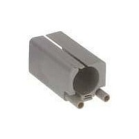
Manufacturer Part Number
09 12 003 3101
Description
Sealed Ethernet Connector
Manufacturer
HARTING
Datasheet
1.09_99_000_0099.pdf
(25 pages)
Specifications of 09 12 003 3101
Connector Type
Sealed Ethernet
Lan Category
Cat5
No. Of Ports
1
Leaded Process Compatible
Yes
Gender
Receptacle
Performance Category
Cat 5e
Usoc Codes
RJ45
Shielding
Unshielded
Housing Material
Plastic
Lead Free Status / RoHS Status
Lead free / RoHS Compliant


Han
00 .
22
Upper current
limit set by
external factors,
i .e . connectable
wire gauge, given
current limit
Current carrying capacity
Current carrying capacity
The current carrying capacity is determined in tests which are
conducted on the basis of the DIN IEC 60 512 part 5 . The current
carrying capacity is limited by the thermal properties of materials
which are used for inserts as well as by the insulating materials .
These components have a limiting temperature which should not
be exceeded .
The relationship between the current, the temperature rise (loss
at the contact resistance) and the ambient temperature of the
connector is represented by a curve . On a linear co-ordinate
system the current lies on the vertical line (ordinate) and the
ambient temperature on the horizontal line (abscissa) which ends
at the upper limiting temperature .
In another measurement the self-heating (∆t) at different currents
is determined .
At least 3 points are determined which are connected to a parabolic
curve, the basic curve .
The corrected current carrying capacity curve is derived from this
basic curve . The reasons for the correction are external factors
that bring an additional limitation to the current carrying capacity,
i .e . connectable wire gauge or an unequal dispersion of current .
Current carrying capacity of copper wires
Example of a current capacity curve
permissible
operation
range
Depiction in accordance with DIN EN 60 204 for PVC-insulated copper wires in an ambient temperature of + 40 °C under permanent operating conditions .
For different conditions and temperatures, installations, insulation materials or conductors the relevant corrections have to be carried out .
B1
B2
C
D
Diameter [mm²] of single wires in a three-phase system
Wires in protective tubes and installation conduits
Cables and wires in protective tubes and installation conduits
Cables and wires at walls
Cables and wires on a bed
basic curve
Type of installation
Permissible upper limiting temperature
corrected curve
set by applied materials
0 .75
7 .60
–
–
–
10 .4
11 .7
11 .5
Definition: The rated current is the continuous, not interrupted
current a connector can take when simultaneous power on all con-
tacts is given, without exceeding the maximum temperature .
Acc . to IEC 61 984 the sum of ambient temperature and the tem-
perature rise of a connector shall not exceed the upper limiting
temperature . The limiting temperature is valid for a complete con-
nector, that means insert plus housing .
As a result the insert gives the limit for the temperature of a com-
plete connector and thus housings as well .
In practice it is not usual to load all terminals simultaneously with
the maximum current . In such a case one contact can be loaded
with a higher current as permitted by the current capacity curve, if
less than 20 % of the whole is loaded .
However, for these cases there are no universal rules . The
limits have to be determined individually from case to case . It is
recommended to proceed in accordance with the relevant rules of
the DIN IEC 60 512 part 5 .
1,0
9 .6
Example of a current carrying curve
13 .5
12,0
15 .2
16 .1
1 .5
Ambient temperature
18 .3
16 .5
21,0
22,0
2 .5
25
23
28
30
4
32
29
36
37
6
Permissible upper temperature-limit
10
44
40
50
52
16
60
53
66
70
set by applied materials
25
77
67
84
88
104
114
35
97
83
Related parts for 09 12 003 3101
Image
Part Number
Description
Manufacturer
Datasheet
Request
R

Part Number:
Description:
Cable Gland (Clamp)
Manufacturer:
HARTING
Datasheet:

Part Number:
Description:
RJ45 ETHERNET CONNECTOR, JACK 5WAY PANEL
Manufacturer:
HARTING
Datasheet:

Part Number:
Description:
RJ45 ETHERNET CONNECTOR, PLUG 8WAY CABLE
Manufacturer:
HARTING
Datasheet:
Part Number:
Description:
Han Brid-RJ45C-female Insulation Body
Manufacturer:
HARTING

Part Number:
Description:
CONN HOUSING 6POS .156 W/O RAMP
Manufacturer:
Molex Inc
Datasheet:

Part Number:
Description:
CONN HOUSING 3POS .156 W/RAMP
Manufacturer:
Molex Inc
Datasheet:

Part Number:
Description:
CONN HOUSING 3POS .156 W/POLAR
Manufacturer:
Molex Inc
Datasheet:

Part Number:
Description:
CONN HOUSING 5POS .156 W/RAMP
Manufacturer:
Molex Inc
Datasheet:

Part Number:
Description:
CONN HOUSING 5POS .156 W/POLAR
Manufacturer:
Molex Inc
Datasheet:

Part Number:
Description:
CONN HOUSING 6POS .156 W/RAMP
Manufacturer:
Molex Inc
Datasheet:

Part Number:
Description:
CONN HOUSING 6POS .156 W/RAMP
Manufacturer:
Molex Inc
Datasheet:

Part Number:
Description:
CONN HOUSING 6POS .156 W/POLAR
Manufacturer:
Molex Inc
Datasheet:

Part Number:
Description:
CONN HOUSING 8POS .156 W/RAMP
Manufacturer:
Molex Inc
Datasheet:

Part Number:
Description:
CONN HOUSING 9POS .156 W/RAMP
Manufacturer:
Molex Inc
Datasheet: