09 12 003 3101 HARTING, 09 12 003 3101 Datasheet - Page 20
09 12 003 3101
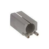
Manufacturer Part Number
09 12 003 3101
Description
Sealed Ethernet Connector
Manufacturer
HARTING
Datasheet
1.09_99_000_0099.pdf
(25 pages)
Specifications of 09 12 003 3101
Connector Type
Sealed Ethernet
Lan Category
Cat5
No. Of Ports
1
Leaded Process Compatible
Yes
Gender
Receptacle
Performance Category
Cat 5e
Usoc Codes
RJ45
Shielding
Unshielded
Housing Material
Plastic
Lead Free Status / RoHS Status
Lead free / RoHS Compliant


Electrical engineering data
Other terms explained
Clearance air gap
The shortest distance through the air between two conductive ele-
ments (see DIN VDE 0110-1, Para . 1 .3 .3) . The air gaps are deter-
mined by the surge voltage withstand level .
Creepage distance
Shortest distance on the surface of an insulating material between
two conductive elements (see DIN VDE 0110-1, Para . 1 .3 .3) . The
creepage distances are dependent on the rated voltage, the pollu-
tion degree and the characteristics of the insulating material .
Working voltage
Fixed voltage value on which operating and performance data
are based . More than one value for rated voltage or rated voltage
range may be specified for the same connector .
Rated impulse voltage
The rated impulse voltage is determined on the basis of the over-
voltage category and the nominal power supply voltage . This level
in turn directly determines the test voltage for testing the overvolt-
age resistance of the connector (Waveform voltage in 1.2/50 µs
as per IEC 60 060-1) .
clearance
creepage
distance
Working current
Fixed current, preferably at an ambient temperature of 40 °C,
which the connector can carry on a permanent basis (without
interruption), passing simultaneously through all contacts which
are in turn connected to the largest possible conductors, with-
out exceeding the upper temperature limit .
The dependence of the rated current on ambient temperature is
illustrated in the respective derating diagrams .
Transient overvoltages
Short-term overvoltage lasting a few milliseconds or less, oscilla-
tory or non-oscillatory, generally heavily damped (see DIN VDE
0110-1, Para . 1 .3 .7 .2) . An overvoltage may occur as a result of
switching activities, a defect or lightening surge, or may be inten-
tionally created as a necessary function of the equipment or com-
ponent .
Power-frequency withstand voltage
A power-frequency overvoltage (50/60 Hz) .
Applied for a duration of one minute when testing dielectric strength .
For test voltages in association with surge voltage withstand lev-
els, see extract from Table 8, DIN EN 61 984 .
Test voltages (Extract from Table 8, DIN EN 61 984)
CTI (Comparative Tracking Index)
This figure gives an indication of the conductivity of insulating
materials and affects the specified creepage distances . The influ-
ence of the CTI value on the creepage distance is as follows: the
higher the index value, the shorter the creepage distance . The
CTI is used to divide plastics into insulation groups .
Breakdown of insulation groups:
Protection levels as per IEC 60 529
The protection level describes the leak-proof character of hous-
ing, e . g . for electrical equipment . It ranges from IP 00 to IP 68 .
HARTING heavy duty Han connectors feature a standard protec-
tion level of IP 65 (see page 00 .09, Table based on DIN VDE 0470,
DIN EN 60 529, IEC 60 529) .
Derating diagram as per DIN IEC 60 512
These diagrams are used to illustrate the maximum current carry-
ing capacity of components . The illustration follows a curve which
shows the current in relation to ambient temperature . Current car-
rying capacity is limited by the thermal characteristics of contacts
and insulating elements which have an upper temperature limit
which should not be exceeded .
Impulse withstand voltage
I
II
IIIa
IIIb
kV (1 .2/50 µs)
12 .0
600 ≤ CTI
400 ≤ CTI < 600
175 ≤ CTI < 400
100 ≤ CTI < 175
0 .5
0 .8
1 .5
2 .5
4 .0
6 .0
8 .0
RMS withstand voltage
kV (50/60 Hz)
0 .37
0 .50
0 .84
1 .39
2 .21
3 .31
4 .26
6 .60
00 .
21
Han
Related parts for 09 12 003 3101
Image
Part Number
Description
Manufacturer
Datasheet
Request
R

Part Number:
Description:
Cable Gland (Clamp)
Manufacturer:
HARTING
Datasheet:

Part Number:
Description:
RJ45 ETHERNET CONNECTOR, JACK 5WAY PANEL
Manufacturer:
HARTING
Datasheet:

Part Number:
Description:
RJ45 ETHERNET CONNECTOR, PLUG 8WAY CABLE
Manufacturer:
HARTING
Datasheet:
Part Number:
Description:
Han Brid-RJ45C-female Insulation Body
Manufacturer:
HARTING

Part Number:
Description:
CONN HOUSING 6POS .156 W/O RAMP
Manufacturer:
Molex Inc
Datasheet:

Part Number:
Description:
CONN HOUSING 3POS .156 W/RAMP
Manufacturer:
Molex Inc
Datasheet:

Part Number:
Description:
CONN HOUSING 3POS .156 W/POLAR
Manufacturer:
Molex Inc
Datasheet:

Part Number:
Description:
CONN HOUSING 5POS .156 W/RAMP
Manufacturer:
Molex Inc
Datasheet:

Part Number:
Description:
CONN HOUSING 5POS .156 W/POLAR
Manufacturer:
Molex Inc
Datasheet:

Part Number:
Description:
CONN HOUSING 6POS .156 W/RAMP
Manufacturer:
Molex Inc
Datasheet:

Part Number:
Description:
CONN HOUSING 6POS .156 W/RAMP
Manufacturer:
Molex Inc
Datasheet:

Part Number:
Description:
CONN HOUSING 6POS .156 W/POLAR
Manufacturer:
Molex Inc
Datasheet:

Part Number:
Description:
CONN HOUSING 8POS .156 W/RAMP
Manufacturer:
Molex Inc
Datasheet:

Part Number:
Description:
CONN HOUSING 9POS .156 W/RAMP
Manufacturer:
Molex Inc
Datasheet: