1658655-1 Tyco Electronics, 1658655-1 Datasheet - Page 5
1658655-1
Manufacturer Part Number
1658655-1
Description
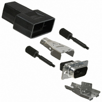
D SUB SHELL, PLUG, SIZE 1, STEEL
Manufacturer
Tyco Electronics
Series
AMPLIMITE HDP-20r
Type
DB09r
Specifications of 1658655-1
Connector Shell Size
1
Connector Body Material
Metal
Body Material
Steel
Gender
Plug
Connector Type
D Sub
Number Of Positions
9
Number Of Rows
2
Flange Feature
Board Side (4-40)
Features
Shielded
Note
Contacts Not Provided
Product
Standard Hoods & Connectors
Number Of Positions / Contacts
9
Shell Plating
Tin over Copper
Shell Size
1
Mounting Style
Cable
Mounting Angle
Straight
Termination Style
Crimp Snap
Housing Material
Nylon
For Use With
HDP-20 Series D Sub Connectors
Lead Free Status / RoHS Status
Lead free / RoHS Compliant
Lead Free Status / RoHS Status
Lead free / RoHS Compliant, Lead free / RoHS Compliant
Other names
A31493
Available stocks
Company
Part Number
Manufacturer
Quantity
Price
Company:

Part Number:
1658655-1
Manufacturer:
TE/AMP
Quantity:
30 000


3.3. Contact Insertion
Terminated contacts are inserted into the back of the connector housing, and snap in place. The cavity rows
are numbered for your convenience. If your design does not require the use of all cavities, the contacts should
be distributed evenly throughout the connector.
3.4. Terminated Strip Length
Terminated strip length shall be as indicated in Figure 3.
3.5. Ferrule Crimp Requirements
Slide the ferrule onto the cable prior to stripping the cable. Keep the larger diameter end of the ferrule toward
the end to be terminated. If the ferrule has only one diameter, no orientation is required. After the wires and
contacts have been terminated slide the ferrule until it is over the braid. Crimp the braid according to the
instructions packaged with the appropriate tooling. See Figure 4 for ferrule crimp requirements.
CONTACT POSN “F” LENGTH
CONTACT POSN “B” LENGTH
Rev D
TERMINATED ASSY LENGTH
TERMINATED STRIP LENGTH
NOTE
NOTE
i
i
15
25
37
50
15
25
37
50
9
9
After inserting a contact into the housing, pull back lightly on the wire to make sure the contact is fully seated.
Trim excess braid flush with front of ferrule with a knife.
33.02 [1.300]
39.12 [1.540]
38.99 [1.535]
48.06 [1.892]
47.65 [1.876]
38.1 [1.500]
F + 0.64 [.025]
Connector
Section D- - D
1.02 [.040] Max
0.38 [.015] Max
Figure 4 (cont’d)
Figure 3
C
B + 1.27 [.050]
Strip Length
Terminated
D
D
E
E
Section E- - E
Braid
Ferrule
B Max
A
114- 40030
5 of 13
Related parts for 1658655-1
Image
Part Number
Description
Manufacturer
Datasheet
Request
R

Part Number:
Description:
Battery Interconnection System for Portable Electronics; BU CONN FS6 8POS DIP TYPE ASSY ( AMP )
Manufacturer:
Tyco Electronics
Part Number:
Description:
Manufacturer:
Tyco Electronics
Datasheet:
Part Number:
Description:
Manufacturer:
Tyco Electronics
Datasheet:


