SM1211E915 Semtech, SM1211E915 Datasheet - Page 24
SM1211E915
Manufacturer Part Number
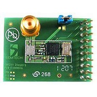
SM1211E915
Description
Dev Kit Accessory
Manufacturer
Semtech
Specifications of SM1211E915
Modulation Type
FSK, OOK
Data Rate Max
200Kbps
Frequency Range
902MHz To 928MHz
Supply Voltage Range
2.1V To 3.6V
Module Interface
SPI
Supply Current
25mA
Accessory Type
RF Module
Sensitivity
-105dBm
Operating Temperature (min)
-40C
Operating Temperature (max)
85C
Operating Temperature Classification
Industrial
Package Type
TQFN EP
Operating Supply Voltage (min)
2.1V
Operating Supply Voltage (typ)
2.5/3.3V
Operating Supply Voltage (max)
3.6V
Sensitivity (dbm)
-105dBm
Rohs Compliant
NA
Lead Free Status / RoHS Status
na
Lead Free Status / RoHS Status
na


or to fill the FIFO buffers with glitch-free data in Buffered mode. The operation of the receiver is now described in
detail.
Note: Image rejection is achieved by the SAW filter.
In receive mode, the RFIO pin is connected to a fixed gain, common-gate, Low Noise Amplifier (LNA). The
performance of this amplifier is such that the Noise Figure (NF) of the receiver can be estimated to be ≈7 dB.
Following the LNA and first down-conversion, there is an IF amplifier whose gain can be programmed from -
13.5 dB to 0 dB in 4.5 dB steps, via the register MCParam_IF_gain. The default setting corresponds to 0 dB gain,
but lower values can be used to increase the RSSI dynamic range. Refer to section 3.4.7 for additional information.
The second mixer stages are followed by the channel select filters. The channel select filters have a strong
influence on the noise bandwidth and selectivity of the receiver and hence its sensitivity. Each filter comprises a
passive and active section.
Each channel select filter features a passive second-order RC filter, with a bandwidth programmable through the
bits RXParam_PassiveFilt. As the wider of the two filters, its effect on the sensitivity is negligible, but its bandwidth
has to be setup instead to optimize blocking immunity. The value entered into this register sets the single side
bandwidth of this filter. For optimum performance it should be set to 3 to 4 times the cutoff frequency of the active
Butterworth (or polyphase) filter described in the next section.
The ’fine’ channel selection is performed by an active, third-order, Butterworth filter, which acts as a low-pass filter
for the zero-IF configuration (FSK), or a complex polyphase filter for the Low-IF (OOK) configuration. The
RXParam_PolypFilt_on bit enables/disables the polyphase filter.
Rev 7 – Sept 2
ADVANCED COMMUNICATIONS & SENSING
3.4.2. LNA and First Mixer
3.4.3. IF Gain and Second I/Q Mixer
3.4.4. Channel Filters
nd
, 2008
3.4.4.1. Passive Filter
3.4.4.2. Active Filter
-f
C
Polyphase filter for OOK ( RXParam_PolyFilt_on=’’1’’ )
-f
3
o
Figure 17: Active Channel Filter Description
*
Low-pass filter for FSK ( RXParam_PolyFilt_on=’’0’’)
Fc
-f
C
ButterfFil
t
BW
Page 24 of 92
0
0
passive
,
filter
the polyphase filter
Canceled side of
4
f
C
*
Fc
ButterFilt
f
f
requency
requency
www.semtech.com
SX1211
Related parts for SM1211E915
Image
Part Number
Description
Manufacturer
Datasheet
Request
R

Part Number:
Description:
Ultra Low Power Integrated Uhf Transceiver Module
Manufacturer:
Semtech Corporation
Datasheet:


Part Number:
Description:
TVS 300W 12V SOT-23
Manufacturer:
Micro Commercial Components (MCC)
Datasheet:

Part Number:
Description:
EVALUATION BOARD
Manufacturer:
Semtech
Datasheet:
Part Number:
Description:
EVALUATION BOARD
Manufacturer:
Semtech
Datasheet:
Part Number:
Description:
VOLTAGE SUPPRESSOR, TRANSIENT SEMTECH
Manufacturer:
Semtech
Datasheet:
Part Number:
Description:
HIGH VOLTAGE CAPACITORS MONOLITHIC CERAMIC TYPE
Manufacturer:
Semtech Corporation
Datasheet:
Part Number:
Description:
EZ1084CM5.0 AMP POSITIVE VOLTAGE REGULATOR
Manufacturer:
Semtech Corporation
Datasheet:
Part Number:
Description:
3.0 AMP LOW DROPOUT POSITIVE VOLTAGE REGULATORS
Manufacturer:
Semtech Corporation
Datasheet:
Part Number:
Description:
Manufacturer:
Semtech Corporation
Datasheet:
Part Number:
Description:
RailClamp Low Capacitance TVS Diode Array
Manufacturer:
Semtech Corporation
Datasheet:
Part Number:
Description:
Manufacturer:
Semtech Corporation
Datasheet:
Part Number:
Description:
Manufacturer:
Semtech Corporation
Datasheet: