MCOG-UPE-1X-DM1 CYAN, MCOG-UPE-1X-DM1 Datasheet - Page 6
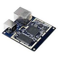
MCOG-UPE-1X-DM1
Manufacturer Part Number
MCOG-UPE-1X-DM1
Description
Enhanced Performance USB/Ethernet Peripheral Module
Manufacturer
CYAN
Datasheet
1.MCOG-UHE-1X-DM1.pdf
(8 pages)
Specifications of MCOG-UPE-1X-DM1
Module Applications
Industrial Communication, Serial To USB Or Ethernet Conversion, Utility Metering, Security Systems
Lead Free Status / RoHS Status
Lead free / RoHS Compliant


Module Connections
The module has the following signals available on two 2x20-way 2mm pitch daughter board
connectors, J4 and J5.
All GPIO pins are configurable as various peripheral pins. The table shows a small subset of the functionality of each.
Refer to the eCOG1X User Manual for a comprehensive list of peripheral options.
V1.0
J4
J5
Pin
1
3
5
7
9
11
13
15
17
19
21
23
25
27
29
31
33
35
37
39
Pin
1
3
5
7
9
11
13
15
17
19
21
23
25
27
29
31
33
35
37
39
Name
Vbus
PortS_0
PortS_2
PortS_4
PortS_6
PortM_0
PortM_2
PortM_4
PortM_6
PortN_0
PortN_2
PortN_4
PortN_6
DAC1
+3.3V
ADC4
ADC3
ADC2
ADC1
+3.3V
Name
+3.3V
NC
PortC_0
PortC_2
PortR_0
PortR_2
PortR_4
PortR_6
eICE_LOADB
eICE_MISO
nReset_Out
PortL_0
PortL_2
PortP_0
PortP_2
PortP_4
PortP_6
PortK_0
PortK_2
+3.3V
eCOG and CyanIDE are registered trademarks of Cyan Holdings plc
Cyan Technology – USB / Ethernet Production Ready Module
Function
+5V supply from USB
GPIO/UART/PWM
GPIO/UART/PWM
GPIO/UART/PWM
GPIO/UART/PWM
GPIO/LCD/PIO/SmartCard
GPIO/LCD/PIO/SmartCard
GPIO/LCD/PIO/SmartCard
GPIO/LCD/PIO
GPIO/LCD/PIO/SmartCard
GPIO/LCD/PIO/SmartCard
GPIO/LCD/PIO/SmartCard
GPIO/LCD/PIO
Analogue output
VDD power supply
Analogue input
Analogue input
Analogue input
Analogue input
VDD power supply
Function
VDD power supply
GPIO/CAP/CNT/I2C/IR
GPIO/CAP/CNT/IR
GPIO/CAP/PWM
GPIO/CAP/PWM
GPIO/CAP/PWM
GPIO/CAP/PWM
DEBUG
DEBUG
DEBUG
GPIO/UART/I2C/IR
GPIO/UART/IR
GPIO/PIO/LCD
GPIO/PIO/LCD
GPIO/PIO/LCD
GPIO/PIO/LCD
GPIO/LCD/I2C/IR
GPIO/LCD/IR
VDD power supply
J4 & J5: Module connections
*
www.cyantechnology.com
*
*
*
*
*
*
*
*
*
*
*
*
*
*
*
*
*
*
*
*
*
*
*
*
*
2
28
30
32
34
36
38
40
4
18
20
40
Pin
4
6
8
10
12
14
16
18
20
22
24
26
Pin
2
6
8
10
12
14
16
22
24
26
28
30
32
34
36
38
Name
GND
PortS_1
PortS_3
PortS_5
PortS_7
PortM_1
PortM_3
PortM_5
PortM_7
PortN_1
PortN_3
PortN_5
PortN_7
DAC2
GND
ADC8
ADC7
ADC6
ADC5
GND
Name
CHASSIS
GND
PortC_1
PortC_3
PortR_1
PortR_3
PortR_5
PortR_7
eICE_MOSI
eICE_CLOCK
nReset_In
PortL_1
PortL_3
PortP_1
PortP_3
PortP_5
PortP_7
PortK_1
PortK_3
GND
Function
GPIO/UART/PWM
GPIO/UART/PWM
GPIO/UART/PWM
GPIO/UART/PWM
GPIO/LCD/PIO/SmartCard
GPIO/LCD/PIO/SmartCard
GPIO/LCD/PIO
GPIO/LCD/PIO
GPIO/LCD/PIO/SmartCard
GPIO/LCD/PIO/SmartCard
GPIO/LCD/PIO/SmartCard
GPIO/LCD/PIO
Analogue output
Analogue input
Analogue input
Analogue input
Analogue input
Function
GPIO/CAP/CNT/I2C/IR
GPIO/CAP/CNT/IR
GPIO/CAP/PWM
GPIO/CAP/PWM
GPIO/CAP/PWM
GPIO/CAP/PWM
DEBUG
DEBUG
DEBUG
GPIO/UART/I2C/IR
GPIO/UART/IR
GPIO/PIO/LCD
GPIO/PIO/LCD
GPIO/PIO/LCD
GPIO/PIO/LCD
GPIO/LCD/I2C/IR
GPIO/LCD/IR
8 December 2008
*
*
*
*
*
*
*
*
*
*
*
*
*
*
*
*
*
*
*
*
*
6 of 8
*
*
*
*
*
Related parts for MCOG-UPE-1X-DM1
Image
Part Number
Description
Manufacturer
Datasheet
Request
R

Part Number:
Description:
USB/Ethernet Gateway Board For ZigBee
Manufacturer:
CYAN
Datasheet:
Part Number:
Description:
USB/Ethernet Gateway Module For ZigBee
Manufacturer:
CYAN
Datasheet:
Part Number:
Description:
USB/Ethernet Gateway Board For Cy-Net3 Over RadioWire
Manufacturer:
CYAN
Datasheet:
Part Number:
Description:
USB/Ethernet Gateway Module For Cy-Net3 Over RadioWire
Manufacturer:
CYAN
Datasheet:
Part Number:
Description:
USB/Ethernet Gateway Board For Wireless M-BUS
Manufacturer:
CYAN
Datasheet:
Part Number:
Description:
USB/Ethernet Gateway Module For Wireless M-BUS
Manufacturer:
CYAN
Datasheet:

Part Number:
Description:
LED 5MM INGAN 505NM CYAN 23DEG
Manufacturer:
Avago Technologies US Inc.
Datasheet:
Part Number:
Description:
LED 5MM INGAN 505NM CYAN 23DEG
Manufacturer:
Avago Technologies US Inc.
Datasheet:

Part Number:
Description:
LED 5MM INGAN 505NM CYAN 30DEG
Manufacturer:
Avago Technologies US Inc.
Datasheet:

Part Number:
Description:
LED 1W STAR MCPCB CYAN INGAN
Manufacturer:
Lite-On Electronics
Datasheet:

Part Number:
Description:
LED SS 3MM CYAN WATER CLEAR
Manufacturer:
Kingbright Corp
Datasheet:

Part Number:
Description:
LED SS 5MM CYAN WATER CLEAR
Manufacturer:
Kingbright Corp
Datasheet:

Part Number:
Description:
LED 5MM INGAN 505NM CYAN 15DEG
Manufacturer:
Avago Technologies US Inc.
Datasheet:
Part Number:
Description:
LED 5MM INGAN 505NM CYAN 15DEG
Manufacturer:
Avago Technologies US Inc.
Datasheet:

Part Number:
Description:
LED 1W CYAN INGAN SMD
Manufacturer:
Lite-On Electronics
Datasheet: