3/4W-140 Cinch Connectors, 3/4W-140 Datasheet - Page 198
3/4W-140
Manufacturer Part Number
3/4W-140
Description
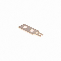
TERMINAL 3/4 W SOLDER 140 SERIES
Manufacturer
Cinch Connectors
Series
140r
Type
Terminal, Solder Tab, Single, Barrier Blockr
Datasheet
1.Y-140.pdf
(282 pages)
Specifications of 3/4W-140
Product
Pins
For Use With/related Products
140 Series
Lead Free Status / RoHS Status
Contains lead / RoHS non-compliant
Color
-
Number Of Positions
-
Lead Free Status / Rohs Status
Lead free / RoHS Compliant
Other names
3/4W140
CBB002
CBB002


Ordering Information
Dura-Con
High Reliability
All-Plastic
Contact Arrangements
(Face view of pin insulator)
(Use reverse order for socket)
** - See p. 5-12 for std. hardware dims. See p. 5-13 for non-std. hardware & p. 5-31 for Mil spec. hardware both sold separately.
***- Length Tolerance: solid wire = ± 3/32”, standard wire = ± 1/4”.
* - Indicates Cinch std. option.
Cinch Dura-Con D Connector
Insulator Type
*D = Thermoplastic
Glass Reinforced
Mounting Type
*A = Screw Mount Flange
No. of Contacts
9, 15, 21, 25, 31, 37, 51
Contact Type
P – Pin (Plug)
S – Socket (Receptacle)
Wire Size in AWG
5 = 25 AWG Solid Copper
6 = 26 AWG Stranded
S = Solder Cup (Skip to Mounting Hardware)
Wire Type
E = MIL-W-16878/4, 7 Strand
C = Solid Copper - Uninsulated
(
Consult factory for non-standard wire types)
DC D A 37 P 6 E 2 -18.0 K
.050" (1.27mm) Density
Solder Cup/Wire
D-Microminiature
5-5
Call Toll Free: 1 (800) 323-9612
Mounting Hardware**
B = No Hardware
F = Float Mount
R = Reverse Float Mount
K = Jackscrew (Standard)
L = Jackscrew (Low Profile)
P = Jackpost, MIL-C-83513/5-07
Lead Length in inches***
00.5 Solid copper wire only
01.0 Solid copper wire only
02.0 Solid copper wire only
18.0 Stranded wire only
24.0 Stranded wire only
36.0 Stranded wire only
48.0 Stranded wire only
Insulation
Color or Wire Finish
*2 = Yellow (Stranded Wire)
*4 = Gold-Plated (Solid Wire Only)
*5 = Color Coded Per MIL-Std. (681)
System 1. (Stranded Wire Only)
1 = White
3 = Tin-Plated
Related parts for 3/4W-140
Image
Part Number
Description
Manufacturer
Datasheet
Request
R


Part Number:
Description:
CONN BARRIER BLOCK COVER 4POS
Manufacturer:
Tyco Electronics
Datasheet:
Part Number:
Description:
CONN BARRIER BLOCK COVER 5POS
Manufacturer:
Tyco Electronics
Datasheet:

Part Number:
Description:
Terminal Block Tools & Accessories COVER FOR 5 POS #6 series
Manufacturer:
Tyco Electronics