3/4W-140 Cinch Connectors, 3/4W-140 Datasheet - Page 128
3/4W-140
Manufacturer Part Number
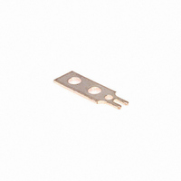
3/4W-140
Description
TERMINAL 3/4 W SOLDER 140 SERIES
Manufacturer
Cinch Connectors
Series
140r
Type
Terminal, Solder Tab, Single, Barrier Blockr
Datasheet
1.Y-140.pdf
(282 pages)
Specifications of 3/4W-140
Product
Pins
For Use With/related Products
140 Series
Lead Free Status / RoHS Status
Contains lead / RoHS non-compliant
Color
-
Number Of Positions
-
Lead Free Status / Rohs Status
Lead free / RoHS Compliant
Other names
3/4W140
CBB002
CBB002


D-subminiature Metal Shell and All Plastic
Solder Cup and IDC
T* Series
Insulator Material: Glass-filled polyester (black), UL 94 V-O rated
Connector Shell: Steel with zinc plating and yellow chromate finish or
Contact Material: Phosphor bronze (stamped)
Contact Plating: Gold flash or 30µin. gold in mating area and gold
Operating Temperature: -65°C to + 125°C
Shock: 50G peak per MIL-STD-202, Method 213, Condition G
Vibration: 12 cycles in three perpendicular directions @ 10-2000Hz, per
Moisture Resistance: 90-95% relative humidity @ 40°C for 96 hours per
Individual Contact Insertion and
Durability: 500 mating cycles
Call Toll Free: 1 (800) 323-9612
Insulation Resistance:
Separation Force (minimum/maximum): 0.7 oz./12 oz.
Withstanding Voltage:
Offered in 9, 15, 25, and 37 position plugs and sockets.
Available in Solder Cup and IDC (insulation displacement) terminations for discrete wire.
Offered with .120 mounting holes.
Approvals:
•
•
See pages 4-5 thru 4-10 for standard dimensions, contact arrangements, and panel
mounting specifications.
Contact Resistance:
UL Recognized - Files E170218 (UL1977) and E130965 (UL1863).
CSA Approved - File LR31996.
Current Rating:
MIL-STD-202, Method 204, Condition D
flash on the remainder. All over nickel.
tin plating (grounding indents on plug)
MIL-STD-202, Method 103
Minimum 1000V RMS @ sea level
3 Amps
2.7 milliohms maximum
5000 megohms maximum (initial);
1000 megohms (minimum) after
environmental testing
4-34
Related parts for 3/4W-140
Image
Part Number
Description
Manufacturer
Datasheet
Request
R


Part Number:
Description:
CONN BARRIER BLOCK COVER 4POS
Manufacturer:
Tyco Electronics
Datasheet:
Part Number:
Description:
CONN BARRIER BLOCK COVER 5POS
Manufacturer:
Tyco Electronics
Datasheet:

Part Number:
Description:
Terminal Block Tools & Accessories COVER FOR 5 POS #6 series
Manufacturer:
Tyco Electronics