V850ES TOUCHIT NEC, V850ES TOUCHIT Datasheet - Page 7
V850ES TOUCHIT
Manufacturer Part Number
V850ES TOUCHIT
Description
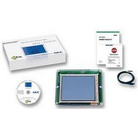
STARTER KIT, 32BIT, TFT LCD
Manufacturer
NEC
Datasheet
1.V850ES_TOUCHIT.pdf
(61 pages)
Specifications of V850ES TOUCHIT
Kit Contents
V850ES/JG2 UPD70F3718 CPU, Epson S1D13A05 LCD/USB Companion Chip, USB Connector
Svhc
No SVHC (18-Jun-2010)
Development Tool Type
Demonstration Kit
Kit Features
Complete Touch Controlled
Silicon Manufacturer
NEC
Kit Application Type
Audio Visual
Application Sub Type
TFT LCD


List of Figures
Figure 1-1 Touch IT! Demonstration kit (without the enclosure) ............................................................10
Figure 4-1 USB connection to the Touch It! board.................................................................................16
Figure 4-2 Touch the opening screen ....................................................................................................16
Figure 4-3 Introduction screens..............................................................................................................17
Figure 4-4 Keyboard and Calibration screens........................................................................................17
Figure 4-5 Bitmap control demo .............................................................................................................18
Figure 5-1 Position of switches on Touch It! circuit board......................................................................20
Figure 5-2 TFT LCD Touch panel display ..............................................................................................22
Figure 6-1 PG-FP4 and MINICUBE2 programmers...............................................................................24
Figure 7-1 Software installation structure...............................................................................................26
Figure 7-2 Structure of demo sub-directory............................................................................................26
Figure 7-3 Structure of Src sub-directory ...............................................................................................27
Figure 8-1 Starting the Application Demo ..............................................................................................28
Figure 9-1 Organisation of software files................................................................................................30
Figure 9-2 Overview of main( )...............................................................................................................33
Figure 9-3 Touch Screen circuit .............................................................................................................38
Figure 9-4 Structure of Segger example containing Maintask( )............................................................39
Figure 10-1 IAR project overview panel .................................................................................................41
Figure 10-2 IAR Projects Option configuration window..........................................................................42
Figure 12-1 MINICUBE2.........................................................................................................................46
Figure 12-2 MINICUBE2 switch settings ................................................................................................47
Figure 12-3 MINICUBE2 connections ....................................................................................................47
Figure 12-4 QB-Programming application and device setup .................................................................48
Figure 13-1 Reconfiguring the linker XCL file.........................................................................................49
Figure 13-2 IAR Debug option setup for the MINICUBE2......................................................................50
Figure 15-1 Epson general configuration ...............................................................................................53
Figure 15-2 Epson preference configuration ..........................................................................................53
Figure 15-3 Epson clock configuration ...................................................................................................54
Figure 15-4 Epson panel configuration ..................................................................................................54
Figure 15-5 Epson panel power configuration........................................................................................55
User's Manual U18781EE1V0UM00
7
Related parts for V850ES TOUCHIT
Image
Part Number
Description
Manufacturer
Datasheet
Request
R

Part Number:
Description:
MCU 32BIT V850ES/JX3 144-LQFP
Manufacturer:
Renesas Electronics America
Datasheet:
Part Number:
Description:
MCU 32BIT V850ES/JX3-E 144-LQFP
Manufacturer:
Renesas Electronics America
Datasheet:
Part Number:
Description:
MCU 32BIT V850ES/JX3-L 80-LQFP
Manufacturer:
Renesas Electronics America
Datasheet:
Part Number:
Description:
MCU 32BIT V850ES/JX3-L 80-LQFP
Manufacturer:
Renesas Electronics America
Datasheet:
Part Number:
Description:
MCU 32BIT V850ES/JX3-L 100-LQFP
Manufacturer:
Renesas Electronics America
Datasheet:
Part Number:
Description:
MCU 32BIT V850ES/LX2 64-LQFP
Manufacturer:
Renesas Electronics America
Datasheet:
Part Number:
Description:
MCU 32BIT V850ES/JX3-L 100-LQFP
Manufacturer:
Renesas Electronics America
Datasheet:
Part Number:
Description:
MCU 32BIT V850ES/LX2 64-LQFP
Manufacturer:
Renesas Electronics America
Datasheet:
Part Number:
Description:
MCU 32BIT V850ES/JX3-L 80-LQFP
Manufacturer:
Renesas Electronics America
Datasheet:
Part Number:
Description:
MCU 32BIT V850ES/JX3-L 80-LQFP
Manufacturer:
Renesas Electronics America
Datasheet:
Part Number:
Description:
MCU 32BIT V850ES/JX3-L 100-LQFP
Manufacturer:
Renesas Electronics America
Datasheet:
Part Number:
Description:
MCU 32BIT V850ES/JX3-L 100-LQFP
Manufacturer:
Renesas Electronics America
Datasheet:
Part Number:
Description:
MCU 32BIT V850ES/HX3 64-LQFP
Manufacturer:
Renesas Electronics America
Datasheet:
Part Number:
Description:
MCU 32BIT V850ES/HX3 80-LQFP
Manufacturer:
Renesas Electronics America
Datasheet:
Part Number:
Description:
MCU 32BIT V850ES/HX3 100-LQFP
Manufacturer:
Renesas Electronics America
Datasheet: