V850ES TOUCHIT NEC, V850ES TOUCHIT Datasheet
V850ES TOUCHIT
Specifications of V850ES TOUCHIT


Related parts for V850ES TOUCHIT

V850ES TOUCHIT Summary of contents
Page 1
... User’s Manual V850ES – Touch It! Demonstration kit for the V850ES/JG2 and NL2432HC22-41K 3.5” TFT Colour LCD Module with touch screen panel Document No. U18781EE1V0UM00 Date Published June 2007 © NEC Electronics Corporation 2007 Printed in Germany ...
Page 2
User's Manual U18781EE1V0UM00 ...
Page 3
... NEC Electronics does not assume any liability for infringement of patents, copyrights or other intellectual property rights of third parties by or arising from the use of NEC Electronics products listed in this document or any other liability arising from the use of such products. No license, express, implied or otherwise, is granted under any patents, copyrights or other intellectual property rights of NEC Electronics or others ...
Page 4
User's Manual U18781EE1V0UM00 ...
Page 5
... Epson S1D13A05 LCD/USB companion chip ......................................................................................21 5.6 TFT Colour LCD display ........................................................................................................................21 5.7 TouchScreen panel................................................................................................................................22 CHAPTER 6 CONNECTORS ............................................................................................................23 6.1 TFT connector J9 ...................................................................................................................................23 6.2 5v power connector J2 ..........................................................................................................................23 6.3 USB connector J8 ..................................................................................................................................23 6.4 Flash Programming connector J4 ........................................................................................................24 CHAPTER 7 SOFTWARE INSTALLATION......................................................................................25 7.1 Touch It! Demonstration kit software installation...............................................................................25 7.2 PC Hardware requirements ...
Page 6
... CHAPTER 13 DEBUGGING THE PROGRAM USING ON-CHIP DEBUG WITH THE MINICUBE2 (OPTIONAL) .................................................................................................................49 13.1.1 XCL Setup........................................................................................................................................49 13.1.2 Disable the UART ............................................................................................................................50 13.1.3 Debug ..............................................................................................................................................50 CHAPTER 14 COLOUR INDEX ..........................................................................................................51 14.1 Colour mapping between the LCD connector and board ...................................................................51 CHAPTER 15 EPSON S1D13A05 CONFIGURATION SETTING ......................................................53 CHAPTER 16 BILL OF MATERIALS..................................................................................................56 CHAPTER 17 SCHEMATICS ..............................................................................................................59 6 User's Manual U18781EE1V0UM00 ...
Page 7
... Figure 1-1 Touch IT! Demonstration kit (without the enclosure) ............................................................10 Figure 4-1 USB connection to the Touch It! board.................................................................................16 Figure 4-2 Touch the opening screen ....................................................................................................16 Figure 4-3 Introduction screens..............................................................................................................17 Figure 4-4 Keyboard and Calibration screens........................................................................................17 Figure 4-5 Bitmap control demo .............................................................................................................18 Figure 5-1 Position of switches on Touch It! circuit board......................................................................20 Figure 5-2 TFT LCD Touch panel display ...
Page 8
... Table 7 Switches on the Touch It! Board ..............................................................................................19 Table 8 Connectors on TFT V850ES board ...........................................................................................20 Table 9 Memory model settings ............................................................................................................32 Table 10 IAR compiler settings ..............................................................................................................43 Table 11 Correct pinning from Epson S1D13A05 to TFT LCD connector ............................................51 Table 12 Actual pinning from Epson S1D13A05 to TFT LCD connector ...............................................52 Table 13 Bill of Materials .......................................................................................................................56 8 List of Tables User's Manual U18781EE1V0UM00 ...
Page 9
... Thank you for choosing NEC Electronics V850ES TFT LCD Touch It! demonstration kit. Whether you are designing a LCD solution for the first time, or you are looking for a solution for your next product, the Touch It! demonstration kit from NEC Electronics can help you see how easy integrate Touch Screen technology into your next design. ...
Page 10
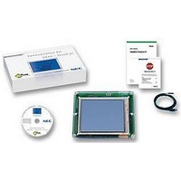
... UART resources or interrupts for the ROM monitor. Figure 1-1 Touch IT! Demonstration kit (without the enclosure) The kit contains all the necessary hardware and software to quickly setup and run and show a number of demos on the TFT Colour LCD. The emWin simulation is also included in the CD to allow emWin to be evaluated on the PC platform without the need for a Touch It! Demonstration board ...
Page 11
... CHAPTER 2 • Touch It! Demonstration kit board containing the V850ES/JG2 µPD70F3718 cpu o Epson S1D13A05 LCD/USB Companion chip o USB connector (connected to S1D13A05 but not used in this demonstration kit) o Buttons to toggle LCD backlight o TFT connector o Programming connector o • NL2432HC22-41K TFT Colour LCD Module 3.5” Super Reflective NLT screen ...
Page 12
GUISimulation executable to show emWin running platform o Also includes sample code which can be compiled with Visual C++ v6.0 or later o • USB cable 12 CHAPTER 2 KIT CONTENTS User's Manual U18781EE1V0UM00 ...
Page 13
... U17715EJ1V0UD00.pdf U17966EE4V0IF00.PDF U18527EJ1V0UM00.PDF http://www.eu.necel.com/update Table 2 TFT colour LCD module nl2432hc22-41k_DOD-MD-0058_1.pdf More information available from http://www.eu.necel.com/products/display/index.html http://www.nec-lcd.com/en/technology/nlt_sr_nlt.html http://www.eu.necel.com/_pdf/EPMC-PU-0018-2.0.PDF Table 3 Segger embOS and emWin documents embOS_Generic.pdf embOS_V850_IAR.pdf emWinUser.pdf More information available from Segger website RELEVANT DOCUMENTATION Table 1 V850ES manuals User Manual for µ ...
Page 14
CHAPTER 3 Table 4 Epson S1D13A05 documents Technical Manual s1d13a05tm.pdf S1D13A05_Hardware_Functional_Spec_Rev_702.pdf Document number X40A-A-001-07 x40ag003.pdf S1D13A05 configuration tool CFG Epson website Complete Schematic Touch_it v2.0 - 25Mar2007.pdf 14 RELEVANT DOCUMENTATION S1D13A05 LCD/USB Companion chip Technical manual X40A-Q-001-1 Hardware Functional Specification ...
Page 15
... CHAPTER 3 Table 6 MINICUBE2 Flash programmer and on-chip debug (not included) Goto http://www.eu.necel.com/update select QB-MINI2-EE MINICUBE2 for 78K0S, 78K0, and 78K0R for latest firmware and select QB-Programmer - to obtain the following installation files MINICUBE2_Firmware_Vxxx.zip MINICUBEUtilities_Vx.xx.zip MQB2ALL_Vxxx.zip QBP_Vxxx.zip PRM-70F3724_Vxxx.zip U18527EJ1V0UM00.pdf U17966EE4V0IF00.PDF U18371EJ1V0UM00.pdf ZUD-CD-06-0044-4-E.pdf ZUD-CD-06-0044-4-E ...
Page 16
... The Touch It! Demonstration kit is preloaded with an introduction software demo that only requires the kit to be connected to 5v using the DC power cable or via the USB connector. (see Table 8 Connectors on TFT V850ES board for the correct jumper connections). Some of the screens are adapted from Segger’ ...
Page 17
... Introduction screens This shows the NEC Electronics introduction screen and a brief slide show of what the Touch It! Demonstration kit can do for you. The demo will continue to the next screen after 20 seconds or when the “Next” button is pressed, 4.1.3 Calibration and Keyboard Screen After the slide show, a calibration program will run allowing you to recalibrate the touchscreen if necessary ...
Page 18
Using bitmaps as buttons The next demo shows bitmaps used as buttons. Click on a bitmap to display a different message at the bottom of the screen. This screen will end after 20 seconds or when “Next” is pressed. ...
Page 19
... For more information, please refer to document listed at the end of Chapter 3. LEDs 5.2 The red led shows that power is applied to the board. A yellow and green led are connected to CPU port pin P97 and P98 respectively and can be used as status lights by the demo software. Switches 5.3 The following switches are available on the board ...
Page 20
... J2 Close pins 1 use this To program the cpu flash memory Pin1 RS232 Rx LCD signals from CPU USB connector – can provide 5v supply to stater kit if J1 pins 2+3 closed TFT connector for LCD ribbon connection User's Manual U18781EE1V0UM00 Reset Unused ADC input select ...
Page 21
... The S1D13A05 supports a “SwivelView” mode which allows the display to be rotated 0 o 270 on the screen. Normally the top edge of the TFT colour LCD display is when the flexible connector is orientated on the lefthand side of the display. The demonstration kit uses the Epson LCD driver in SwivelView so o that the display is rotated 90 making the edge with the flexible connector the top edge ...
Page 22
... For more details on the TFT colour LCD display with touchscreen panel, please refer to the TFT LCD datasheet listed in Chapter 3. Caution: The Touch screen display flex ribbon connector is fragile. Take care not to bend or crease the flex ribbon to avoid damage. Section 9.6.3 briefly describes how the touchscreen is setup to read each respective touchscreen axis. ...
Page 23
... USB connector J8 6.3 The USB connector is to provide an alternative 5 volt power source to the Touch It! Demonstration kit. Before connecting the USB cable, ensure the jumper settings are correct for J1 in Chapter 4. The USB functionality can be provided by the Epson S1D13A05 LCD companion chip, but the USB driver is not available at present, therefore this function is not enabled for the Touch It! Demonstration kit ...
Page 24
... PG-FP4 Universal Flash programmer – (not included with Touch It! Demonstration kit) Figure 6-1 PG-FP4 and MINICUBE2 programmers The programming voltage for the V850ES Flash is supplied by the PG-FP4 or by the MINUCBE2 when SW2 is switched to ‘3’ not necessary to apply power via the USB connector or J2. 24 CHAPTER 6 ...
Page 25
... The pre-loaded introductory demonstration kit demo will run on the Touch It! Demo board when 5 volts is applied via the mini-USB connector. To examine, edit additional software demos or recompile and run the standalone Segger example files, the demonstration kit software includes the EWV850-KS16 Kick Start version of the IAR V850 software development tools (limited to 16Kbytes application code) ...
Page 26
CHAPTER 7 Structure of Software installation 7.5 Figure 7-1 Software installation structure Figure 7-2 Structure of demo sub-directory 26 SOFTWARE INSTALLATION User's Manual U18781EE1V0UM00 ...
Page 27
CHAPTER 7 SOFTWARE INSTALLATION Figure 7-3 Structure of Src sub-directory User's Manual U18781EE1V0UM00 27 ...
Page 28
... Application demo. 8.2 A washing machine application demo is provided on the software installation under the project directory Washingmachine\debug\exe. To view the code, start the IAR EWV850-KS16 tools and open the Touch It! project workspace and then select the TouchItDemo2 project. Figure 8-1 Starting the Application Demo ...
Page 29
CHAPTER 8 Segger examples. 8.3 A sample of Segger examples for emWin are also included in the software installation which can also be compiled and run on the Touch It! demonstration kit. Please note that not all Segger examples will ...
Page 30
CHAPTER 9 Basic structure of software demo 9.1 This document is not intended to describe how to use embOS and emWin but will describe how the Touch It! Demonstration kit demo code is built on this and what is required ...
Page 31
... These libraries are built to enable applications to be compiled using the special KS16 version of the IAR tools. (Please note that the regular library files in the trial download will not compile with the KS16 IAR tools, and require the full version of the IAR tools which require additional licensing.) The emWin library included in the Touch It! Demonstration kit also contains trial optionals of Memory Devices, Window Manager and Widgets ...
Page 32
CHAPTER 9 This demonstration kit includes a number of software demos which shows you the potential possibilities you can use to develop your product into The demo software is designed as individual tasks which runs on embOS and calls the ...
Page 33
CHAPTER 9 Demo code overview 9.3 The demo code has a basic structure called from main( ). Main( ) performs the majority of the initialisation, setups the interrupt enabled before creating the MainTask, User Task, TouchScreen initialisation, before handing over ...
Page 34
CHAPTER 9 Main 9.4 The functions contained in main perform the following:- Disable the interrupt prior to hw and OS initialisation. The OS initialisation is performed by a function called OS_INIT the RTOSInit_V850ES_JG2.c file. (RTOSInit_V850ES_JG2_no_uart.c is used in ...
Page 35
... Next the TFT LCD hardware registers are configured by calling a macro function “TFT_POWER_ON_COMMAND” (source found in TFTReg_Setting.h). The sequence of data and timeouts required when setting up the TFT registers are detailed in the NECEL TFT LCD user manual. 9.4.3 Initialising the Epson S1D13A05 LCD companion chip The LCD companion chip is initialised when LCD_Init called by the function GUI_Init emWin library ...
Page 36
... This file also includes flags to determine if the X and Y axis need to be swapped or mirrored. The Touch It! Demonstration kit is configured so that the top edge is the TFT side with the FPC flexible connector strip. Creating tasks 9.6 The Segger trial version of embOS is provided and is limited to a maximum of 3 tasks ...
Page 37
CHAPTER 9 9.6.1 MainTask This task is created in main( ). MainTask( ) forms the framework for the Touch It! Demos which are described in the next section 9.7 When you wish to examine other examples in the Segger sample ...
Page 38
... To read the X-axis value of the touchscreen on the V850ES ADC input ANI0, the cpu port lines connected to the X-axis P.XL and P.XR are place in high-impendence input mode and a voltage is applied to the resistive array on the Y-axis by setting the cpu port lines connected to P.YU high in output mode and setting P.YD low in output mode. ...
Page 39
CHAPTER 9 Once the touchscreen has been initialised, the emWin touchscreen API calls can be used to detect where the touchscreen is pressed or a button drawn on the display has been clicked, e.g. GUI_Getket GUI_TOUCH_Getstate( ). The ...
Page 40
... CHAPTER 9 The demo functions called are:- TouchIt_intro, • NECEE_intro, • TouchIt_Slide1, • TouchIt_Slide2, • Display_blockdiagram, • Display_SeggerIAR_logo, • TouchIt_Slide3, • TouchIt_Slide4, • Keyboard_Calibration, • Display_Application_Bitmaps, These demos show how text and values can be written to the display and how bitmap graphics can be shown and also used as bitmapped buttons for use by the touch panel. The bitmap graphics are embedded in the ‘ ...
Page 41
... CHAPTER 10 IAR tools 10.1 Start the IAR Embedded Workbench tools for NEC V850 by clicking on the Windows Start button:- Start->All Programs->IAR Systems->IAR Embedded Workbench for NEC V850 or click on the icon on the Windows desktop. To open the demo project workspace, click on File->Open->WorkSpace and then browse to the \Project directory and open the ...
Page 42
... CHAPTER 10 STARTING THE IAR TOOLS Compiler and linker settings 10.2 Once the project is open, confirm the compiler and linker settings by clicking on Projects->Options to open the “Options” configuration window Figure 10-2 IAR Projects Option configuration window This section lists the key settings for the compiler environment which need to be changed from the default setting ...
Page 43
... CHAPTER 10 STARTING THE IAR TOOLS Defines Linker Output Extra output Diagnostics List Config Processing Compiling a project 10.3 First, highlight a project by clicking on the project tab in the Project Window. To rebuild the project, click on Project->Make or Project->Clean and then Project->Rebuild All icon. ...
Page 44
... Adding project groups Open the V850 IAR tools with the supplied “TouchIt_project.eww” workspace. You will see a panel with the tab “overview” on the bottom. Click on the top PROJECT level to put it into context and then open the menu Project->Create New Project. In the Create New Project Window, select V850 family + empty project and click “ ...
Page 45
CHAPTER 11 TO SETUP A NEW IAR PROJECT 11.1.2 Adding files to the project groups Next you need to add the source files for each group, add the files from the directories shown below. • CPU_V850ES \Sampleprograms\Project\Src\CPU_V850ES_JG2\DF3718_HWInit.s85 o \Sampleprograms\Project\Src\CPU_V850ES_JG2\ o ...
Page 46
... The MINICUBE2 diagnostics user’s manual ZUD-CD-06-0044-4-E.pdf and MINICUBE2 On-chip debug checker user’s manual ZUD-CD-06-0044-4-E.pdf is also included in the installation. When you connect the MINCUBE2 to your PC for the first time via USB, you will be prompted to install a USB driver which can be found in the directory C:\Program Files\NEC Electronics Tools\mqb2all . ...
Page 47
... V850. Figure 12-2 MINICUBE2 switch settings To use the MINICUBE2 as a flash programmer, ensure the MINCUBE2 is connected to connector J4 on the Touch It! board using the 2x8 way cable and to the PC using the USB cable. Ensure the MINICUBE2 USB driver is installed before starting the QBP program. ...
Page 48
... CHAPTER 12 USING THE MINICUBE2 (OPTIONAL) To start the QBP program, goto Start->All Programs->NEC Electronics Tools->QBP2. Next, install the PRM file for the 70F3718 from the Device->Setup menu. The programmer is ready for use. Figure 12-4 QB-Programming application and device setup To program a hex file to the Touch It! demonstration kit:- Firstly, select File-> ...
Page 49
... If you have purchased a MINICUBE2 and wish to debug your code running on the Touch It! kit with the V850 IAR kickstart tools, you will need to use the MINICUBE2 using the On-chip debug facility. You will need to ensure the correct linker XCL file is used and UART is disabled in the code as described below before recompiling ...
Page 50
... Before you can start debugging, ensure that the MINICUBE2 USB driver is installed and the latest MINICUBE2 firmware is upgraded as decribed in Chapter 12 Connect the MINICUBE2 according to the manual U18371EJ1 pdf file Ensure the IAR debug options are selected for the MINICUBE2 Figure 13-2 IAR Debug option setup for the MINICUBE2 ...
Page 51
... FP_DAT9 (Red2) FP_DAT10 (Red1) FP_DAT11 (Red0) FP_DAT12 (Green2) FP_DAT13 (Green1) FP_DAT14 (Green0) FP_DAT15 (Blue2) FP_DAT16 (Blue1) FP_DAT17 (Blue0) Table 11 Correct pinning from Epson S1D13A05 to TFT LCD connector COLOUR INDEX CHAPTER 14 -> LCD pin 30 (Red5) -> LCD pin 29 (Red4) -> LCD pin 28 (Red3) -> ...
Page 52
... Table 12 Actual pinning from Epson S1D13A05 to TFT LCD connector The Segger libraries provide the low level drivers to handle normal pinout as in Table 11, but when non-standard connections are used, alternative functions need to be used to handle the remapping of colour signals when writing the data to the Epson device. To achieve, this alternative functions LCD_Color2Index_User and LCD_COLOR LCD_Index2Color_User which reinvert the red and green colour signals ...
Page 53
EPSON S1D13A05 CONFIGURATION SETTING CHAPTER 15 This chapter contains 5 screenshots showing the settings used for the Epson S1D13A05 initialisation. The tool is obtained from Epson and creates the correct values to use in the initialisation of the device. The ...
Page 54
CHAPTER 15 EPSON S1D13A05 CONFIGURATION SETTING Figure 15-3 Epson clock configuration Figure 15-4 Epson panel configuration 54 User's Manual U18781EE1V0UM00 ...
Page 55
CHAPTER 15 EPSON S1D13A05 CONFIGURATION SETTING Figure 15-5 Epson panel power configuration User's Manual U18781EE1V0UM00 55 ...
Page 56
CHAPTER 16 This section lists the components used on the Touch It! Circuit board. Quantity No. /per Reference Board C1,C8,C10,C11 C3, C5,C16,C17,C18,C19,C20 C21,C22,C23,C24,C25,C26 C32,C33,C34,C35,C36,C37 C38,C39,C40,C41 7 4 ...
Page 57
... SWITCH, DIL 1/2 PITCH SMD 8 WAY IC, SM LED DRIVER ADJUSTABLE 2way 1 row side entry header, S2B-EH (LF) (SN) expension connector 20wayx2row, 2.00mm pitch Connector 8 way x 2 row vertical through hole header HEADER, VERT 1 ROW 5 WAY; HARWIN M52- 040000P0545 HEADER, VERT 2 ROW 40 WAY; ...
Page 58
... TPS76925DBVT (0.1A)n DBV Package uPD70F3718GC-8EA-A 512KByte of flash memory STM1001TWX6F SOT23- 3 74HC138/SO SO16 SP3232EBCA-L SSOP16 S1D13A05 LCD Controller 128-pin QFP5 package SN74HC244DW NC38 watch crystal, through hole 32.768kHz 12.50pF Citizen Crystal, through hole HC49US5.000MABJ-UB Citizen Crystal, through hole HC49US48.000MABJ-UB 3.5" NEC TFT Display ...
Page 59
SCHEMATICS CHAPTER 17 User's Manual U18781EE1V0UM00 59 ...
Page 60
CHAPTER 17 SCHEMATICS User's Manual U18781EE1V0UM00 ...
Page 61
CHAPTER 17 SCHEMATICS User's Manual U18781EE1V0UM00 61 ...