RS08KA2 PROMO Freescale Semiconductor, RS08KA2 PROMO Datasheet - Page 22
RS08KA2 PROMO
Manufacturer Part Number
RS08KA2 PROMO
Description
DEMO KIT, SILICON BUNDLE, RS08KA2
Manufacturer
Freescale Semiconductor
Datasheet
1.RS08KA2_PROMO.pdf
(34 pages)
Specifications of RS08KA2 PROMO
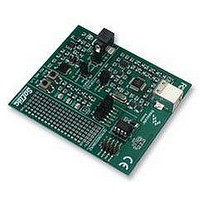
Kit Contents
DEMO9RS08KA2 Board, USB Cable, Quick Start Guide, User Manual, Packing List
Svhc
No SVHC (15-Dec-2010)
Development Tool Type
Demonstration Kit
Kit Features
RS08KA2 Microcontroller,
Silicon Manufacturer
Freescale
Core Architecture
RS08
Core Sub-architecture
RS08
Silicon Core Number
MC9RS08
Silicon Family Name
RS08KA
Rohs Compliant
Yes
Lead Free Status / RoHS Status
Lead free / RoHS Compliant


Emulated ADC Application Example
2
In this section the analog comparator module in the MC9RS08KA2 is used to implement an 8-bit
analog-to-digital (ADC).
In many applications, precise ADC operation is not needed. With a timer module and a low cost high
performance analog comparator module built into the MCU, an ADC can be emulated. The emulated ADC
resolution depends on the resolution of the timer. In the case of MC9RS08KA2 an 8-bit modulo timer
(MTIM) is included, hence an 8-bit ADC operation can easily be emulated. Comparing with a dedicated
ADC module the trade-off is the sampling time and the dynamic range. Emulated ADC usually has longer
sampling time, narrower dynamic range, and rail-to-rail operation is not feasible.
Figure 2-5
connected to a RC network and the negative terminal is the ADC input. Before the comparator function is
enabled, both terminals are general I/O ports. The positive terminal is initially set to output low to
discharge the RC. When ADC function is required, the comparator is then enabled. The ADC function is
emulated by comparing the ADC input to the voltage across the C. Timer is used to monitor the time it
takes for the RC to charge up to the ADC input voltage. Since the RC charging profile is not linear, if the
ADC dynamic range is small, the timer reading can be used as it is. In general it is more desirable to
convert the timer reading back to linear scale using a simple lookup table.
2.1
The following is the procedure to use the MC9RS08KA2 to perform the emulated ADC function. The
complete program is listed in Appendix A.
22
1. Define the sampling time and timer resolution. The sampling time is the time for the RC to
charge up to the maximum ADC input voltage (dynamic range). In this example one millisecond
is arbitrarily chosen. When 8-bit timer is used (n=8), the timer resolution is 3.9µs (the function is
given in
period becomes 255 times 4µs, i.e. 1.02ms.
Emulated ADC Application Example
Implementation
shows the schematic of a simple emulated ADC. The positive terminal of the comparator is
Equation
1) and is rounded up to 4µs. Maximum timer overflow is assumed, then overflow
TimerResolution
Figure 2-5. Emulated ADC Schematic
MCU Boundary
On-chip
Comparator
Getting Started with RS08, Rev. 1
+
–
=
Ch
--------------------------------------- -
VDD
arg
2
eUpTime
n
R
4k7
C
47nF
–
1
ADC In
Freescale Semiconductor
Eqn. -1
Related parts for RS08KA2 PROMO
Image
Part Number
Description
Manufacturer
Datasheet
Request
R

Part Number:
Description:
Manufacturer:
Freescale Semiconductor, Inc
Datasheet:
Part Number:
Description:
Manufacturer:
Freescale Semiconductor, Inc
Datasheet:
Part Number:
Description:
Manufacturer:
Freescale Semiconductor, Inc
Datasheet:
Part Number:
Description:
Manufacturer:
Freescale Semiconductor, Inc
Datasheet:
Part Number:
Description:
Manufacturer:
Freescale Semiconductor, Inc
Datasheet:
Part Number:
Description:
Manufacturer:
Freescale Semiconductor, Inc
Datasheet:
Part Number:
Description:
Manufacturer:
Freescale Semiconductor, Inc
Datasheet:
Part Number:
Description:
Manufacturer:
Freescale Semiconductor, Inc
Datasheet:
Part Number:
Description:
Manufacturer:
Freescale Semiconductor, Inc
Datasheet:
Part Number:
Description:
Manufacturer:
Freescale Semiconductor, Inc
Datasheet:
Part Number:
Description:
Manufacturer:
Freescale Semiconductor, Inc
Datasheet:
Part Number:
Description:
Manufacturer:
Freescale Semiconductor, Inc
Datasheet:
Part Number:
Description:
Manufacturer:
Freescale Semiconductor, Inc
Datasheet:
Part Number:
Description:
Manufacturer:
Freescale Semiconductor, Inc
Datasheet:
Part Number:
Description:
Manufacturer:
Freescale Semiconductor, Inc
Datasheet: