EICEUSB1X CYAN, EICEUSB1X Datasheet - Page 8
EICEUSB1X
Manufacturer Part Number
EICEUSB1X
Description
ADAPTER, USB DONGLE, EICE
Manufacturer
CYAN
Datasheet
1.EICEUSB1X.pdf
(15 pages)
Specifications of EICEUSB1X
Development Tool Type
Programming Adapter
Kit Contents
USB Lead, CyanIDE CD, Ribbon Cable
Kit Contents Descriptive
USB Lead, CyanIDE CD, Ribbon Cable
Kit Features
Cyan ECOG1X5A5 Device Provides USB
Accessory Type
USB Debug Adaptor
Rohs Compliant
Yes
Lead Free Status / RoHS Status
Lead free / RoHS Compliant
For Use With
Host PC System And ECOG Target Board


2.1
2.2
23 January 2008
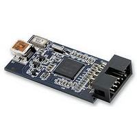
The eCOG1X USB eICE adaptor uses the Cyan eCOG1X5A5 device to implement the USB
interface to the host PC system. A standard USB cable connects to the host side of the unit
via a mini-B USB socket. The PC end of the cable has a type A USB connector fitted. The
eICE connection to the eCOG1X target device is via a 10-way boxed header that connects
to the target hardware, either via a ribbon cable to a boxed header, or directly into a 10-way
socket. The eCOG1X5A5 device provides the USB interface to the host PC and digital
inputs and outputs for the eICE signals.
Configuration data including serial numbers, USB PID and VID numbers, and identifier
strings is stored in the eCOG1X internal flash memory. This configuration data is required to
allow the unit to identify itself to the host PC during the USB device enumeration process,
and for the PC then to select the correct device driver files. The Cyan USB eICE adaptors
are loaded with the required configuration data during functional test.
The adaptor is powered from the +5V supply available on the host USB connection. Local
on-board regulators provide 3.3V and 1.8V for the eCOG1X device, and for the I/O
connections to the eCOG1X target device.
All signals to the target device eICE conection include 100Ω series resistors. The LOADB
signal also includes a 1kΩ pull-up resistor. The USB +5V supply is also connected to the
10 way header; this may be used to power small target systems provided the total current
drawn is within the 500mA limit available from a standard USB host. If this is used to power
the target system, then a suitable low dropout 3.3V regulator must be fitted. Decoupling
capacitors must be connected to both the input and output of this regulator according to the
manufacturer’s recommendations.
The software drivers for the USB eICE adaptor are included in the CyanIDE development
package. CyanIDE V1.4.3 or later includes the required version of the driver files as
standard.
To ensure that the driver files are present, install the CyanIDE software and any necessary
updates before connecting the eICE adaptor to the host PC. Further details about the
software installation are shown later in this document.
Note that any previous version of CyanIDE should be uninstalled before the latest version is
installed. This includes any USB device drivers for Cyan products such as the evaluation
board, which should be removed via the Device Manager. Installing the new version of
CyanIDE also reinstalls the USB eICE device driver.
Hardware
Software
Cyan Technology Ltd
Page 3
Related parts for EICEUSB1X
Image
Part Number
Description
Manufacturer
Datasheet
Request
R

Part Number:
Description:
LED 5MM INGAN 505NM CYAN 23DEG
Manufacturer:
Avago Technologies US Inc.
Datasheet:
Part Number:
Description:
LED 5MM INGAN 505NM CYAN 23DEG
Manufacturer:
Avago Technologies US Inc.
Datasheet:

Part Number:
Description:
LED 5MM INGAN 505NM CYAN 30DEG
Manufacturer:
Avago Technologies US Inc.
Datasheet:

Part Number:
Description:
LED 1W STAR MCPCB CYAN INGAN
Manufacturer:
Lite-On Electronics
Datasheet:

Part Number:
Description:
LED SS 3MM CYAN WATER CLEAR
Manufacturer:
Kingbright Corp
Datasheet:

Part Number:
Description:
LED SS 5MM CYAN WATER CLEAR
Manufacturer:
Kingbright Corp
Datasheet:

Part Number:
Description:
LED 5MM INGAN 505NM CYAN 15DEG
Manufacturer:
Avago Technologies US Inc.
Datasheet:
Part Number:
Description:
LED 5MM INGAN 505NM CYAN 15DEG
Manufacturer:
Avago Technologies US Inc.
Datasheet:

Part Number:
Description:
LED 1W CYAN INGAN SMD
Manufacturer:
Lite-On Electronics
Datasheet:

Part Number:
Description:
LED, HIGH BRIGHTNESS, CYAN, 160LM
Manufacturer:
LUMILEDS
Datasheet:

Part Number:
Description:
LED, HIGH BRIGHTNESS, CYAN, 130LM
Manufacturer:
LUMILEDS
Datasheet:

Part Number:
Description:
LED, HIGH BRIGHTNESS, CYAN, 5W, 160LM
Manufacturer:
LUMILEDS
Datasheet:
Part Number:
Description:
LED, HIGH BRIGHTNESS, CYAN, 80LM
Manufacturer:
LUMILEDS
Datasheet:

Part Number:
Description:
LED, HIGH BRIGHTNESS, CYAN, 60LM
Manufacturer:
LUMILEDS
Datasheet:

Part Number:
Description:
LED High Power (> 0.5 Watts) Cyan 1 Watt Star PCB
Manufacturer:
Seoul Semiconductor Inc